


- 11 -
3.13 Install the speed control rod assembly (linkage with the yoke installed on one end)
into the end of the speed control lever located underneath the center of the
console. Insert the end of the linkage (opposite the yoke) into the end of the speed
control lever from the right hand side and fasten with a hairpin cotter from bolt bag.
3.14 Connect the lower end of the speed control linkage to the speed control crank
located at the top rear of the fuel tank support. Secure with clevis pin and hairpin
cotter from bolt bag.
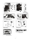
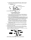
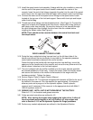
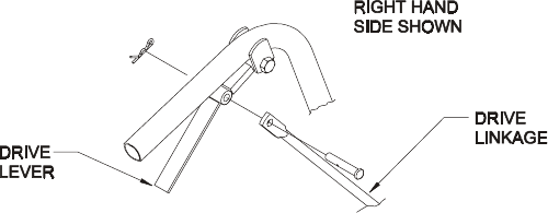
3.15 Thread each drive linkage into the threaded swivel. (See Figure 3). Connect the
upper end of each drive linkage to the drive levers. Fasten with a long clevis pin
and hairpin cotter from bolt bag. Be sure the clevis pin is first inserted through
the drive linkage and then through the drive lever from the outside before
installing the hairpin cotter (See Figure 4).
NOTE: There should not be a washer between the neutral lock latch and
the hairpin cotter.
FIG. 4
DRIVE LINKAGE TO DRIVE LEVER
3.16 Route the long unattached wiring harness lead, up the left hand side of the
handle and connect the two terminals (in any order) to the operator presence
control switch terminals underneath the control console.
Fasten the lead to the handle with two large wire ties from bolt bag, one at the
upper end of the handle next to the console, and one at the very lower end of the
handle where it attaches to the fuel tank support.
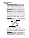
3.17 The unit is shipped with the muffler installed onto the engine exhaust manifold
but rotated rearward to fit the crate. Loosen the clamp, rotate the muffler ahead
and secure the bracket on the muffler to the bracket on the engine with the
hardware provided. Tighten the clamp.
3.18 Service Engine: Refer to Engine Owner’s Manual.
3.19 Service Hydraulic Oil: The machine is shipped with hydraulic oil filled to the top of
the baffles in the reservoir. Run the machine for approximately 15 minutes to
allow any extra air to purge out of the hydraulic system. Check hydraulic
reservoir and if necessary fill the reservoir to the appropriate level with Mobil 1
15W-50 synthetic motor oil.
3.20
GREASE UNIT: NOTE:
UNIT IS NOT GREASED AT THE FACTORY.
Refer to 5.1.13, for locations and grease amounts.
3.21 Follow pre-start instructions as outlined in 4.2.
NOTE: After starting the engine and engaging the hydro drive, if either of
the drive wheels acts sluggish or will not rotate at all, stop engine and
refer to Section 5.1.10 on the Hydraulic System Air Purge procedure.
3.22 Perform any needed adjustments as outlined in the Adjustment Section.