


- 9 -
2.11 TORQUE REQUIREMENTS
BOLT LOCATION TORQUE
Blade/Cutter Housing Spindle Bolt.................................75-80 ft-lbs.
Caster Bracket Mounts ..................................................30-35 ft-lbs.
Cutter Deck/Engine Deck Mount....................................30-35 ft-lbs.
Engine Mounting Bolts (Kohler & Kawasaki)..................25-30 ft-lbs.
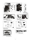
3. ASSEMBLY INSTRUCTIONS
3.1 Uncrate unit, leaving it on the pallet, place upper handle assembly, fuel tank, and
drive linkages at the rear of the machine. Place casters at the front of unit.
3.2 Place a length of 4" x 4" block between the front of the cutter deck and the pallet.
3.3 Remove the bolt bag from the top of the fuel tank support.
3.4 Loosen the 5/16" hardware at the two (2) discharge deflector hinge points so that
the deflector is snug, but can be moved up and down freely.
3.5 Refer to Parts Manual to help you identify and locate parts and their proper position.
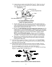
3.6 Install casters to front of deck using appropriate hardware from the bolt bag
(eight 3/8 x 3/4" bolts and eight 3/8" whizlock nuts); tightening the lower four
bolts first, then the top four.
3.7 Apply retaining adhesive “Fel-Pro Prolock Retaining I or Retaining II” or “Loctite
RC 609 or 680” on the two threaded studs from the bolt bag and install into the
two left holes underneath fuel tank. Install the fuel tank on top of the fuel tank
support with the studs going through the slots in the support. Install two 5/16 x
3/4 screws with a 5/16 SAE flatwasher and 5/16 lockwasher into the threaded
holes in the right side of the fuel tank.
Do not over-tighten
. Place a 5/16” SAE
flatwasher, then a spring, over each of the studs and fasten with a 5/16 nyloc
nut. Tighten the 5/16 nylock nut fully than back off a 1/2 turn. This is to allow for
normal fuel expansion and contraction with changes in temperature and fuel
levels.
Do not over-tighten
.
3.8 Attach the fuel tank hose to the tank fitting and secure with the clamp provided.
Make sure that fuel hose is not between engine and throttle plate on engine.
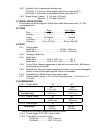
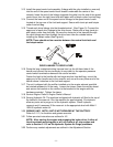
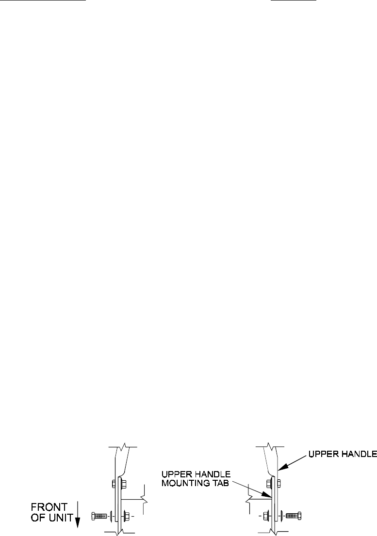
3.9 Position the lower end of the handle assembly on the outsideof the upper rear
section of the fuel tank & handle support.
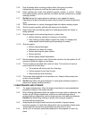
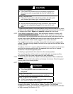
Install four 3/8-16 x 1" bolts (with four spring disk washers against the head of each
bolt) from the outside in. Secure using four 3/8" whizlock nuts on the inside of each
handle support and tighten until the spring disk washers are flat (See Figure 1).
FIG. 1
UPPER HANDLE MOUNTING
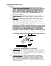
3.10 Route the throttle cable along the right side of the upper handle, under the fuel
tank support, and position the cable on the
left
side of the engine.
Attach throttle cable to engine:
a) Position the throttle control lever (on console) in the full throttle (but not
choke) position. You will feel a detent when the throttle lever is
approximately 3/4”from the upper end of the slot (this is full throttle position).