


- 31 -
4. The spring that keeps tension on the knob should normally not need
adjustment. However, if adjustment is needed, adjust to where length
of spring is about 1” between washers. Adjust spring length by
turning nut at front of spring.
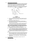
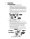
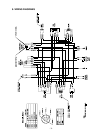
d) Drive Lever Linkage Adjustment
1. With rear of machine still on jack stands and engine running at full
throttle, move the speed control lever to the midway position. Move the
respective drive lever upward until it reaches the neutral position and
engage neutral lock latches. See Figure 4. If the tire rotates in either
direction, the length of the drive lever linkage will need to be adjusted.
2. Adjust the linkage length by loosening the jam nuts at both ends of
the linkage and rotating the linkage in the ball joints. Lengthen the
linkage if the tire is turning in reverse and shorten the linkage if the
tire is creeping forward. Tighten the jam nuts at both ends. Release
and re-engage the neutral lock checking that the tire stops. Continue
this process until the tire is at a dead stop.
3. Make this adjustment for both sides.
e) Tracking Adjustment
1. Stop engine and wait for all moving parts to stop. Raise rear of machine,
remove jack stands, and carefully lower machine to the ground.
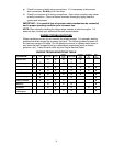
2. Check the drive tire pressures and tire circumferences. See 5.1.12.
3. Run the unit and observe the tracking on a level, smooth, hard
surface such as concrete or asphalt.
4. If the unit tracks to one side or the other, turn the quick track knob.
Turn the knob right to “steer” right, turn the knob left to “steer” left.
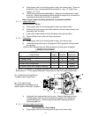
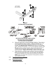
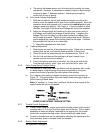
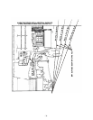
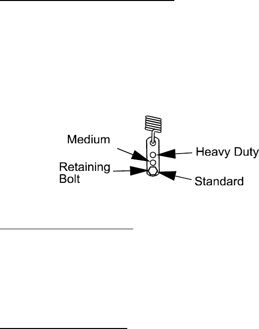
5.2.6 Hydro Pump Spring Tension Setting
a) For medium or heavy duty drive conditions such as operation with a sulky
on steep slopes, a higher spring force may be required on the hydro
pump control arms to prevent the drive system from stalling.
b) For a heavier drive setting, relocate the spring anchor link as shown in
Figure 12. The spring anchor links are located under the engine deck on
the left and right hand sides.
Note: In “medium” or “heavy duty” positions, the drive lever forces at the
upper handle will also be increased.
FIGURE 12
HYDRO PUMP SPRING TENSION SETTING
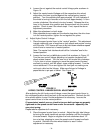
5.2.7 Throttle Control Adjustment
a) Loosen cable clamp on engine and position throttle control (at the control
console) within 1/4" (6 mm) from the upper end of the slot. Pull on cable
assembly at lower end where it attaches to the engine until the throttle
control arm contacts the stop screw. Secure cable with cable clamp.
b) Tension in throttle lever can be adjusted by adjusting the tightness of the
lever pivot bolt, which is located under the console.
5.2.8 Electric Clutch Adjustment
No adjustment necessary.