


- 29 -
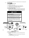
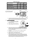
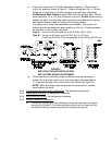
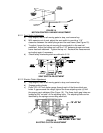
c) Adjust anti-scalp rollers for Normal Operating Conditions. Place rollers in
one of the positions shown in Figure 9. Rollers will maintain 3/4 in. (19 mm)
clearance to the ground to minimize gouging and roller wear or damage.
For Maximum Deck Flotation, place rollers one hole position lower. Rollers
should maintain 1/4 in. (6.4 mm) clearance to ground. Do Not adjust rollers to
support the deck. Be sure roller bolts and nuts are installed with the spring
disc washer between head of the bolt and mounting bracket.
Two types of anti-scalp roller assemblies are available. See Figure 9 to
determine which assembly has been installed on the unit. Torque hardware
as specified, or loss of roller may result.
Type A – Torque the 3/8 whizlock nut to 40-45 ft-lbs. (54-61 N-m)
Type B – Torque the 3/8 nyloc nut to 30-35 ft-lbs. (41-47 N-m)
Torque the 3/8-24x2 Gr 8 hex capscrew to 50-55 ft-lbs (68-75 N-m)
FIGURE 9
ANTI-SCALP ROLLER INSTALLATION
AND CUTTING HEIGHT ADJUSTMENT
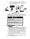
d) When operating in extremely rough conditions it may be necessary to
position the anti-scalp rollers one or two holes higher than described in
"c" to prevent damage to the rollers and/or bolt failure (See Figure 9).
NOTE: When anti-scalp rollers are placed in these positions, reduced
deck flotation will result.
6.2.2 Transmission drive belt tension adjustment
: No adjustment necessary.
6.2.3 Mower deck drive belt
: No adjustment necessary.
6.2.4 Blade drive belt tension
. No adjustment necessary.
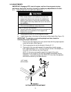
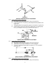
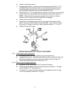
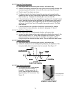
6.2.5 Neutral Centering Adjustment
a) The Neutral Centering Device adjustment should be made with the engine
running at full throttle. First raise and securely block up the frame so that
the drive wheels can rotate freely without contacting the ground.