Maintenance
pressure to the lever allow the reverse indicator
spring to bring the levers back to neutral. The
wheel must stop turning or slightly creep in
reverse (Figure 17).
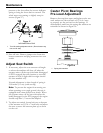
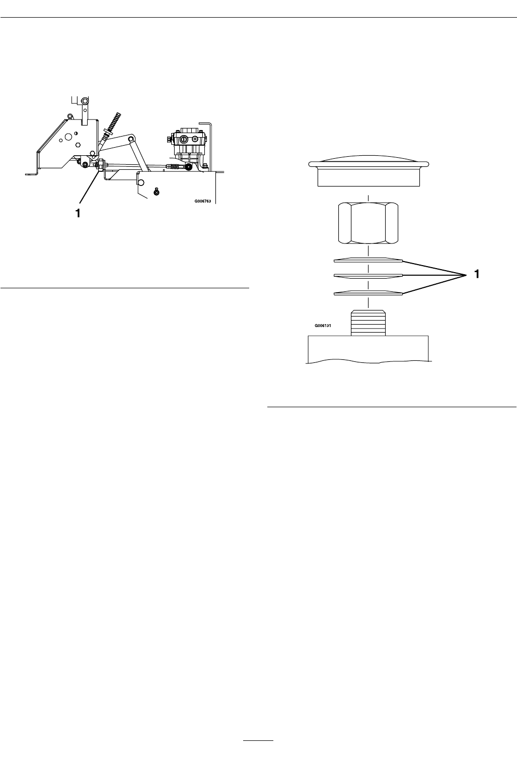
Figure 17
Left-Hand Side of Unit
1. Turn LH tracking adjustment knob. (Do not loosen any
nuts on LH side)
11. Shut off unit. Remove jumper wire from wire
harness connector and plug connector into seat
switch.
Adjust Seat Switch
1. If necessary, adjust the seat actuator rod length
to where the machine will shut off when the
operator raises off the seat (with brake disengaged
or PTO engaged) but will continue to run with
operator in seat (a slight shift in weight should
not shut machine off).
Normal adjustment is when length of spring is
2.09 inches (5.3 cm) (with seat up).
Note: To prevent the engine from cutting out
when operating over rough ground, the unit is
equipped with a time-delayed seat switch. When
the operator raises off the seat with either the
brake disengaged or the PTO engaged, the engine
should stop after 1/2 second has elapsed.
2. To adjust seat switch, loosen lock nut on bottom
of the actuator rod (5/16 x 7 inch bolt) and adjust
the nuts to move the actuator plate up or down
on the rod.
Caster Pivot Bearings
Pre-Load Adjustment
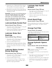
Remove dust cap from caster and tighten nyloc nut
until washers are at and back off 1/4 of a turn
to properly set the pre-load on the bearings. If
disassembled, make sure the spring disc washers are
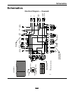
reinstalled as shown in Figure 18.
Figure 18
1. Spring disc washers
36


