


Maintenance
Motion Control Linkage
Adjustment
WARNING
Engine must be running and drive
wheels must be turning so motion control
adjustment can be performed. Contact with
moving parts or hot surfaces may cause
personal injury
Keep ngers, hands, and clothing clear of
rotating components and hot surfaces.
CAUTION
Raising the mower deck for service or
maintenance relying solely on mechanical
or hydraulic jacks could be dangerous. The
mechanical or hydraulic jacks may not be
enough support or may malfunction allowing
the unit to fall, which could cause injury.
Do Not rely solely on mechanical or hydraulic
jacks for support. Use adequate jack stands
or equivalent support
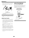
1. This adjustment must be made with the drive
wheels turning. First raise the frame and block up
so that drive wheels can rotate freely.
2. Remove the electrical connection from the seat
safety switch, located directly to the left of the seat
switch assembly beside the hydraulic oil reservoir.
3. Temporarily install a jumper wire across the
terminals in the connector of the main wiring
harness.
4. Run the unit at least 5 minutes with the drive
levers at full forward speed to bring hydraulic
system oil up to operating temperature.
5. Unhook seat latch and tilt seat forward.
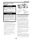
6. Loosen lock nuts from the ball joints at each end
of the RH pump control linkage (Figure 16).
Note: The nuts to the rear of the unit on each
rod have left-hand threads.
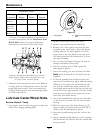
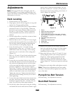
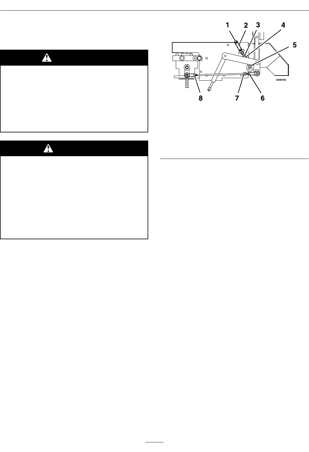
Figure 16
1. Turn bolt here
5. End of slot
2. Reverse indicator
6. Loosen here (right-hand
thread)
3. Loosen here 7. Turn here to adjust
4. Yoke
8. Loosen here (left-hand
thread)
7. Start engine. Brake must be engaged and
motion control levers out to start engine.
Operator does not have to be in the seat
because of the jumper wire being used.Run
engine at full throttle and release brake.
8. The reverse indicator spring must be correct
before the following adjustments can be made.
See the Reverse Indicator Adjustment section.
Note: The motion control lever needs to be in
neutral while making any necessary adjustments.
9. Bring the motion control lever into the neutral
position. Adjust RH pump control rod length
by rotating the double nuts on the rod in the
appropriate direction until the wheels slightly
creep in reverse (Figure 16). Move the motion
control lever to the reverse position and while
applying slight pressure to the lever, allow the
reverse indicator spring to bring the levers back to
neutral. The wheel must stop turning or slightly
creep in reverse.
The left rod assembly controls the left wheel and
the right rod assembly controls the right wheel.
10. Adjustment for the RH motion control lever:
Bring the RH motion control lever into the
neutral position.
Bring the LH motion control lever into the
neutral position. Adjust the LH pump control rod
length by rotating the tracking adjustment knob in
the appropriate direction until the wheels slightly
creep in reverse. Move the motion control lever
to the reverse position and while applying slight
35