


Operation
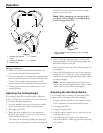
Drive wheel release valves are used to release the
hydrostatic drive system to allow the machine to be
pushed without the engine running. Unhook seat
latch and tilt seat up to gain access to pumps.
With a 5/8 inch wrench, turn both valves one turn
counterclockwise to release drive system. Turn
clockwise to reset system. Do Not overtighten. Do
Not tow machine.
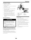
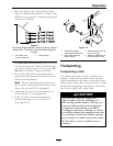
Tracking Adjustment Knob
Located under the seat on the LH pump control link.
Rotating this knob allows ne tuning adjustments so
that the machine tracks straight with the drive levers
in the full forward position.
Stop machine and wait for all moving parts to stop.
Engage park brake. Unhook seat latch and tilt seat
forward to gain access to the tracking knob. Rotate
the knob clockwise (as viewed from the rear of the
machine) to cause the machine to track more to the
right and counterclockwise to cause the machine
to track more to the left. Adjust in quarter-turn
increments until the machine tracks straight. Check
that the machine does not creep when in neutral with
the park brakes disengaged.
Important: Do Not rotate the knob too far, as
this may cause the machine to creep in neutral.
Refer to the Motion Control Linkage Adjustment
section in Maintenance.
PTO Engagement Switch
Located on the right fuel tank.
Switch must be pulled out to the “ROTATE”
position to engage the blades. Switch is pushed in to
the “STOP” position to stop the blades.
Pre-Start
Fill fuel tanks. For best results use only clean, fresh
regular grade unleaded gasoline with an octane rating
of 87 or higher. Regular grade leaded gasoline may
also be used; however, combustion chamber and
cylinder head will require more frequent service. See
Engine Owner’s Manual.
Do Not add oil to gasoline.
Do Not overll fuel tank. Never ll the fuel tank so
that the fuel level rises above a level that is 1/2 inch
(13 mm) below the bottom of the ller neck to allow
for fuel expansion and prevent fuel spillage.
Make sure you understand the controls, their
locations, their functions, and their safety
requirements.
Refer to the Maintenance section and perform all the
necessary inspection and maintenance steps.
Operating Instructions
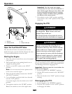
Raise the Rollover Protection System
(ROPS)
Important: Lower the roll bar only when
absolutely necessary.
1. Remove the hairpin cotter pins and remove the
two roll bar pins (Figure 5).
2. Raise the roll bar to the upright position and
install the two pins and secure them with the
hairpin cotter pins (Figure 5).
Important: Always use the seat belt with the
roll bar in the raised position. Ensure that the
rear part of the seat is secured with the seat
latch.
19