


Maintenance
Brake Link Adjustment
Check to make sure brake is adjusted properly.
1. Disengage brake lever (lever down).
2. Measure the length of the spring. Measurement
should be 2 3/4 inches (7.0 cm) between washers.
(Figure 15).
3. If adjustment is necessary, tighten the nut directly
below the yoke and loosen the bottom nut
(bottom one of the two tightened together) below
the spring. Turn the nut directly below the washer
(top nut of the two tightened together) until the
correct measurement is obtained. Tighten the two
nuts together and repeat on opposite side of unit.
Turn clockwise to shorten spring length and turn
counterclockwise to lengthen the spring.
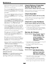
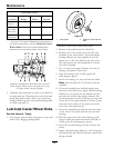
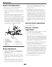
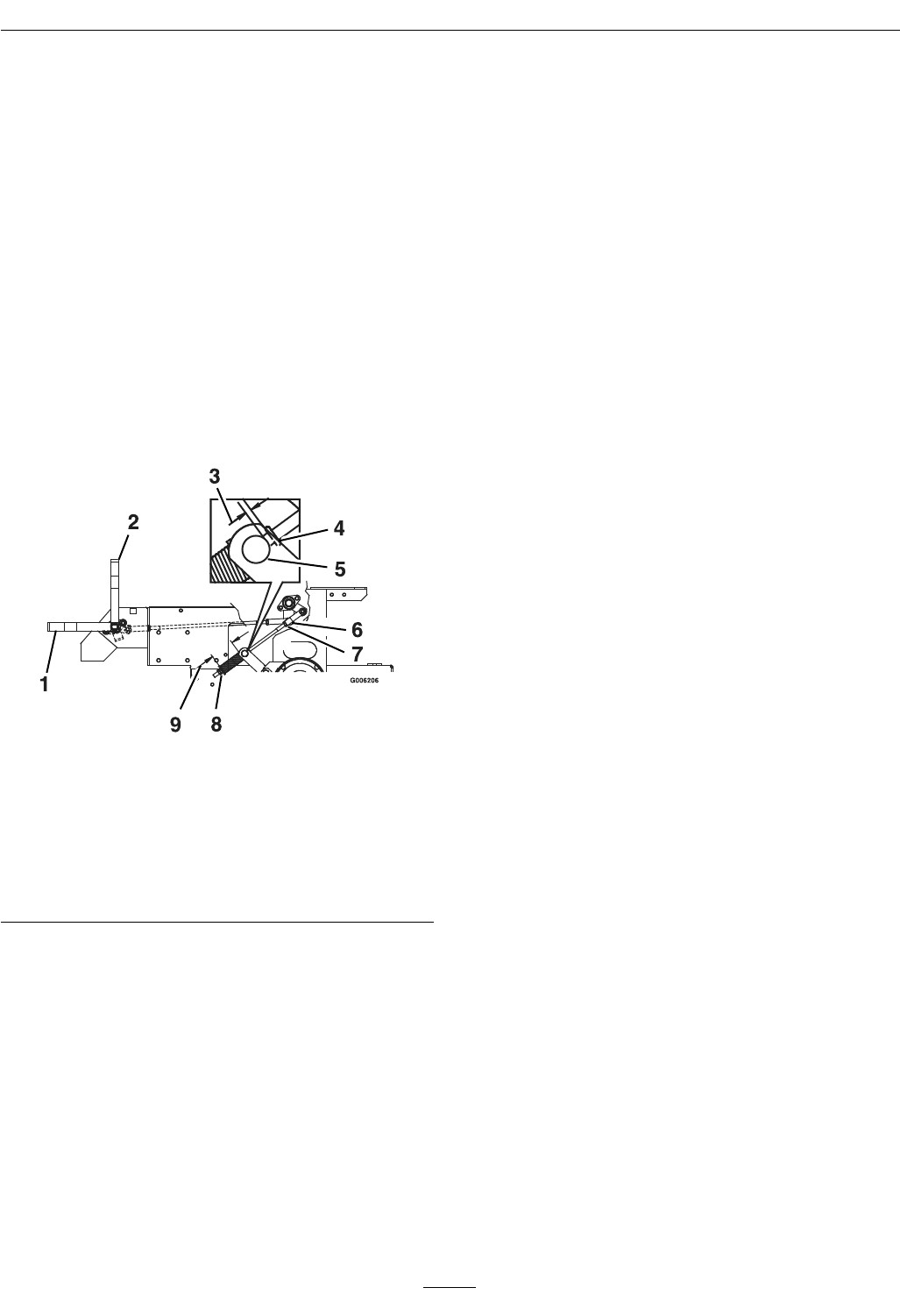
Figure 15
1. Lever down
(disengaged)
6. Yoke
2. Lever up (engaged)
7. Lock nut
3. 1/4 to 5/16 inch (6.4 to
7.9 mm)
8. Spring adjustment
4. Collar 9. 2.75 inches (7.0 cm)
5. Trunnion roller
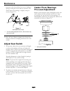
Brake Adjustment
1. Check for brake link 2 3/4 inches (7.0 cm)
measurement as described in the Brake Link
Adjustment section.
2. Engage the brake lever (lever up). The space
between the trunnion roller and the rod collar
should measure 1/4 inch to 5/16 inch (6.4–7.9
mm).
3. If adjustment is necessary, loosen nut above the
trunnion roller. Adjust the nyloc nut under the
trunnion roller until distance listed above exists
between the spring retainer bracket and the
adjacent nyloc nut. Tighten the jam nut above
the trunnion roller.
4. If adjustment is necessary, loosen the nut
directly below the yoke. Turn the bottom nut
(below washer) until the correct measurement
is obtained see Figure 15 turn nut clockwise to
lengthen the gap (screws rod into yoke) and turn
counterclockwise to shorten the gap (screws
rod out of yoke). Tighten nut against yoke and
check opposite side of unit, repeat if necessary.
Lengthen (or shorten) the brake rod until the
correct gap can be achieved by following steps
2 and 3.
Electric Clutch Adjustment
No adjustment necessary.
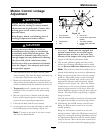
Reverse Indicator
Adjustment
1. Stop engine, wait for all moving parts to stop, and
remove key. Engage parking brake.
2. Unhook seat latch and tilt seat forward.
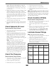
3. Begin with either the left or right motion control
lever. Move lever to the neutral position and pull
lever back until the clevis pin (on arm below pivot
shaft) contacts the end of the slot (just beginning
to put pressure on spring). (Figure 16).
4. Check where lever is relative to notch in console
(should be centered allowing lever to pivot
outward to the neutral lock position).
5. If adjustment is needed, loosen the nut against the
yoke and while applying slight rearward pressure
on the motion control lever, turn the head of the
adjustment bolt in the appropriate direction until
lever is centered (keeping rearward pressure on
the lever will keep the pin at the end of the slot
and allow the adjustment bolt to move the lever
to the appropriate position). Tighten lock nut.
6. Repeat on opposite side of unit.
34