


Maintenance
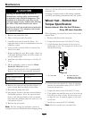
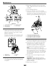
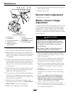
Figure 32
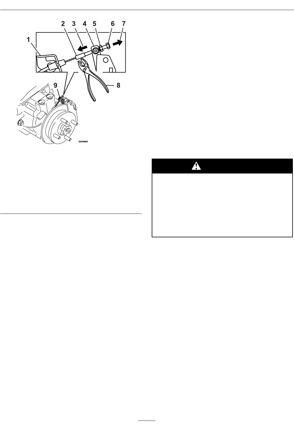
Left Hand Brake Shown
1. Cable anchor
6. Lock nut
2. Threaded rod 7. Pull cable threaded rod
this direction
3. Push lever this direction 8. Hold threaded rod here
4. Caliper lever arm 9. Swivel (pivot head)
5. Standard nut (shown
against swivel)
Note the order of the standard nut and lock nut
(no nut on the cable anchor side of the swivel).
10. Release hold on the caliper lever and cable. The
wheel hub should turn by hand in both directions
relative to the caliper; some friction/resistance
is acceptable.
11. If there is no movement between the hub rotor
and the caliper then back off the standard nut one
turn from the swivel and repeat step 10 (drive
release valves must be in the “released” position
on the hydros).
12. If the hub rotor moves very freely relative to the
caliper, then tighten the standard nut one turn
against the swivel and repeat step 10.
13. Once step 10 is achieved, hold the threaded rod
end with a tool and tighten the lock nut against
the standard nut. Do Not allow the cable to turn
when the nuts are tightened.
14. Rotate the drive wheel release handle to the
“operating” position. Refer to the Drive Wheel
Release Valves section in Operation.
15. Repeat on the opposite side of machine.
16. Install the rear tires and torque lug nuts to 90-95
ft-lb (122-129 N-m).
17. Remove jack stands.
Electric Clutch Adjustment
No adjustment necessary.
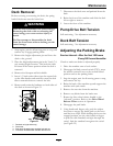
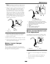
Motion Control Linkage
Adjustment
Located on either side of the fuel tank, below the seat
are the pump control linkages. Rotating the pump
linkage with a 1/2 inch wrench allows ne tuning
adjustments so that the machine does not move in
neutral. Any adjustments should be made for neutral
positioning only.
WARNING
Engine must be running and drive
wheels must be turning so motion control
adjustment can be performed. Contact with
moving parts or hot surfaces may cause
personal injury.
Keep ngers, hands, and clothing clear of
rotating components and hot surfaces.
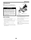
1. Prior to starting the engine, push the deck lift
pedal and remove the height of cut pin. Lower
deck to the ground.
2. Raise the rear of machine up and support with
jack stands (or equivalent support) just high
enough to allow drive wheels to turn freely.
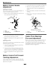
3. Remove the electrical connection from the seat
safety switch, located under the bottom cushion
of the seat. The switch is a part of the seat
assembly.
4. Temporarily install a jumper wire across the
terminals in the connector of the main wiring
harness.
5. Start engine. Brake must be engaged and
motion control levers out to start engine.
Operator does not have to be in the seat
because of the jumper wire being used. Run
engine at full throttle and release brake.
6. Run the unit at least 5 minutes with the drive
levers at full forward speed to bring hydraulic oil
up to operating temperature.
42