


Operation
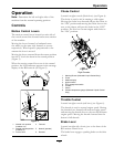
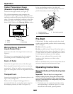
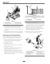
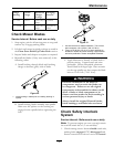
Figure 17
1. Deck foot pedal 3. Cut of height decal
2. Height adjustment pin 4. Transport lock control
5. Insert the height adjustment pin into the hole
corresponding to the desired cutting height.
See the decal on the side of the deck lift plate for
cut heights.
6. Push the deck lift pedal, release the transport lock
and allow the deck to lower to the cutting height.
Adjusting the Anti-Scalp Rollers
It is recommended to change the anti-scalp roller
position, when the height of cut has changed.
1. Stop the machine and move the motion control
levers outward to the neutral lock position.
2. Disengage the PTO.
3. Engage the park brake.
4. Stop the engine, remove the key and wait for all
moving parts to stop.
5. Adjust the anti-scalp rollers by removing the
bushing, spring disc washer and bolt.
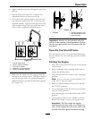
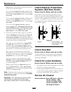
6. Place the rollers in one of the positions shown
(Figure 18). Rollers will maintain 3/4 inch (19
mm) clearance to the ground to minimize gouging
and roller wear or damage.
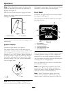
Figure 18
For cutting heights above 3.5 inches (90 mm) use the
bottom hole. The rollers will still be effective against
scalping.
1. Anti-scalp roller
mounting bracket
2. Cutting height
For Maximum Deck Flotation, place the rollers
one hole position lower. Rollers should maintain
1/4 inch (6.4 mm) clearance to the ground. Do
Not adjust the rollers to support the deck.
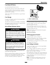
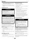
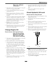
7. Be sure the roller bolts are installed with the
spring disc washer between the head of the bolt
and the mounting bracket (Figure 19).
8. Torque the 3/8–24 x 2 Gr 8 hex capscrew to
50–55 ft-lb (68–75 N-m) (Figure 19).
Figure 19
1. Spring disc washer
(cone towards bolt head)
3. 3/8 nyloc-torque to 30-35
ft-lb (41-47 N-m)
2. Front right anti-scalp
bracket shown
4. 3/8-24 x 2 GR8 torque to
50-55 ft-lb (68-75 N-m)
26