


Maintenance
Deck Removal
Before servicing or removing the deck, the spring
loaded deck arms must be locked out.
WARNING
Deck lift arm assemblies have stored energy.
Removing the deck with out releasing the
stored energy can cause serious injury or
death.
Do Not attempt to disassemble the deck
from the front frame without locking out the
stored energy.
1. Stop engine, wait for all moving parts to stop, and
remove key. Engage parking brake.
2. Remove the height adjustment pin and lower the
deck to the ground.
3. Place the height adjustment pin in the 3 inch (7.6
cm) cutting height location. This locks the deck
lift arms in the lowest position when the deck is
removed.
4. Remove the oorpan and belt shields.
5. Insert 1/2 inch socket driver into the square hole
on the idler bracket and carefully rotate the deck
idler counterclockwise to remove the belt.
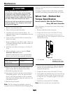
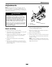
6. Remove and retain the hardware on both sides of
the deck as shown in Figure 31.
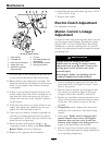
Figure 31
1. Panhard rod (right side only)
2. Deck strut
3. Rear deck lift attachment shoulder bolt and nut.
4. Front deck lift attachment shoulder bolt and nut.
7. Disconnect the deck strut and panhard from the
deck.
8. Raise the front of the machine and slide the deck
left or right to remove.
9. Lower the front of the machine.
Pump Drive Belt Tension
Self-tensioning - No adjustment necessary.
Deck Belt Tension
Self-tensioning - No adjustment necessary.
Adjusting the Parking Brake
Service Interval: After the rst 100 hours
Every 500 hours thereafter
Check to make sure brake is adjusted properly.
1. Drive the machine onto a level surface.
2. Disengage the blade control switch (PTO), move
the motion control levers to the neutral locked
position and set the parking brake.
3. Stop the engine, wait for all moving parts to stop,
and remove the key.
4. Raise the back of the machine up and support the
machine with jack stands.
5. Remove the rear tires from the machine.
6. Remove any debris from the brake area.
7. Rotate the drive wheel release handle to the
“released” position. Refer to the Drive Wheel
Release Valves section in Operation.
8. Disengage the park brake.
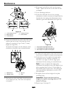
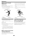
9. Using hands and ngers only, push the caliper
lever arm to engage the brake pads on the rotor
until the lever stops. While holding the lever at the
stopped position, use the other hand or ngers
to pull the cable threaded end tight through the
swivel. Spin the standard nut against the swivel
(see Figure 32).
41