


Maintenance
loose enough to be moved comfortably by the
operator.
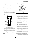
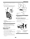
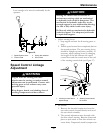
Figure 16
1. Speed Control Lever 3. Spring disc washers
2. Friction Plate 4. Hex locknut
Speed Control Linkage
Adjustment
WARNING
Engine must be running and drive
wheels must be turning so motion control
adjustment can be performed. Contact with
moving parts or hot surfaces may cause
personal injury.
Keep ngers, hands, and clothing clear of
rotating components and hot surfaces.
CAUTION
Raising the mower deck for service or
maintenance relying solely on mechanical
or hydraulic jacks could be dangerous. The
mechanical or hydraulic jacks may not be
enough support or may malfunction allowing
the unit to fall, which could cause injury.
Do Not rely solely on mechanical or hydraulic
jacks for support. Use adequate jack stands
or equivalent support.
• Adjust steering levers
1. Stop engine and wait for all moving parts to
stop.
2. Pull the speed control lever completely back to
the neutral position. The two steering levers
should be straight up and down (vertical). If
necessary, adjust steering levers by changing
the length of the link between the speed
control lever and the control arm on the end
of the steering control shaft (see Figure 17).
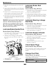
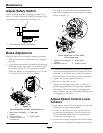
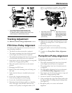
Figure 17
1. Loosen jam nuts here to
adjust linkage
2. Steering levers should
be vertical
• Set neutral:
1. Remove the electrical connection from the
seat safety switch, located directly in front of
the seat switch assembly.
2. The neutral adjustment must be made with
the drive wheels turning. Raise the frame and
place on jack stands so that drive wheels can
rotate freely. Temporarily install a jumper wire
33