


Maintenance
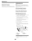
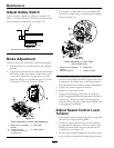
Adjust Safety Switch
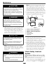
Adjust all safety switches so plunger extends 3/16
inch to 1/4 inch (4.8 mm-6.4 mm) from switch body
when plunger is compressed (see Figure 13).
Figure 13
1. 3/16 inch to 1/4 inch (4.8 mm-6.4 mm)
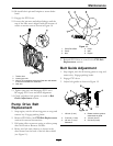
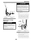
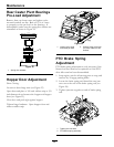
Brake Adjustment
Check to make sure each brake is adjusted properly.
1. Pull the brake lever up and back to the engaged
position.
2. A gap must exist between the bottom of the brake
bolt head and the top surface of the brake swivel
as shown in Figure 14. If a gap does not exist,
adjust the linkage to a maximum gap of 1/2 inch
±1/8 inch (1.3 cm ±0.33 cm) as shown.
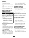
Figure 14
Brake Adjustment for Each Side (Separately)
1. Brake Lever in engaged
position
4. Brake Bolt
2. Loosen nut here
5. Brake Swivel
3. 1/2 inch ±1/8 inch (1.3
cm ±0.33 cm)
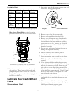
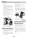
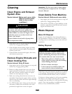
3. The brakes on both sides can be simultaneously
adjusted by lengthening or shortening the linkage
shown in Figure 15.
Figure 15
Brake Adjustment for Both Sides
(At the same time)
1. Brake Lever in engaged
position
3. Rotate yoke
2. Remove clevis pin 4. Loosen nut here
4. If individual adjustment is necessary, loosen the
jam nut on the brake bolt that is against the clevis
connected to the brake arm on the wheel motor.
Turn the brake bolt to achieve proper adjustment.
5. Tighten the jam nut against the clevis.
6. Repeat for other side of unit.
7. Engage and disengage the brakes to check for
proper engagement and disengagement. Readjust
if necessary. When the brakes are disengaged,
there should be free play in the brake linkage with
no dragging in the brakes.
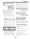
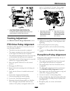
Adjust Speed Control Lever
Tension
1. Stop engine, wait for all moving parts to stop, and
remove key. Engage parking brake.
2. Tension in speed control lever can be adjusted
by adjusting the tightness of the lever pivot bolt,
which is located under the seat near the speed
control lever (see Figure 16).
3. Set the tension high enough that the speed control
lever position is maintained during operation and
32