


Maintenance
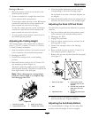
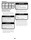
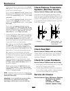
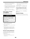
Figure 20
1. Positive (+) cable on discharged battery
2. Positive (+) cable on booster battery
3. Negative (–) cable on the booster battery
4. Negative (–) cable on the engine block
5. Booster battery
6. Discharged battery
7. Engine block
4. Connect the other end of the positive cable to the
positive terminal of the booster battery.
5. Connect the black negative (–) cable to the other
terminal (negative) of the booster battery.
6. MAKE THE FINAL CONNECTION ON
THE ENGINE BLOCK OF THE STALLED
VEHICLE (NOT TO THE NEGATIVE POST)
AWAY FROM THE BATTERY. STAND BACK.
7. Start the vehicle and remove the cables in the
reverse order of connection (the engine block
(black) connection is the rst to disconnect).
Check Mower Blades
Service Interval: Before each use or daily
1. Stop engine, wait for all moving parts to stop, and
remove key. Engage parking brake.
2. Lift deck and secure in raised position as stated in
the Clean Grass Build-Up Under Deck section.
3. Inspect blades and sharpen or replace as required.
4. Reinstall the blades (if they were removed) in the
following order:
A. Install the blade onto the spindle shaft.
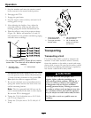
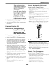
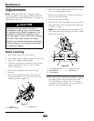
Figure 21
1. Spindle
2. Blade
3. Blade drive washer
4. Blade bolt washer assembly — Torque to 55-60 ft-lb
(75-81 N-m) Apply lubricant to threads as needed to
prevent seizing. Copper-based anti-seize preferable.
Grease acceptable substitute.
B. Apply lubricant to the threads of the blade
bolt as needed to prevent seizing. Copper
based anti-seize is preferable. Grease is an
acceptable substitute.
C. Install the blade drive washer and blade bolt
washer assembly into the spindle. Make sure
the hex in the washer is engaged on the
spindle before tightening the bolt. Install
blade bolt nger tight.
D. Place wrench on the top spindle nut then
torque the blade bolts to 55-60 ft-lb (75-81
N-m).
WARNING
Incorrect installation of the blade or
components used to retain the blade can
be dangerous. Failure to use all original
components and assembled as shown could
allow a blade or blade component to be
thrown out from under the deck resulting in
serious personal injury or death.
Always install the original Exmark blades,
blade bushings, and blade bolts as shown.
Check Safety Interlock
System
Service Interval: Before each use or daily
Note: To prevent engine cut-outs on rough terrain
the seat kill switch has a 1/2 second delay.
1. Check starting circuit. Starter should crank with,
parking brake engaged, PTO disengaged and
31