


Operation
Drive Wheel Release Valves
WARNING
Hands may become entangled in the rotating
drive components below the engine deck, which
could result in serious injury or death.
Stop engine, remove key, allow all the moving
parts to stop before accessing the drive wheel
release valves.
WARNING
The engine and hydraulic drive units can become
very hot. Touching a hot engine or hydraulic
drive units can cause severe burns.
Allow the engine and hydraulic drive units to
cool completely before accessing the drive wheel
release valves.
Located on the back of the unitized hydraulic drive
units, below the engine deck.
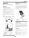
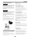
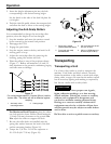
During normal operating conditions, the drive wheel
release valves are positioned horizontally. If the
machine has to be pushed by hand, the valves must
be in the “released” position (see
Figure 9).
Figure 9
1. Handle in “released” position
2. Handle in “operating” position
To release the drive system (see item 1 in Figure 9),
rotate the handle 1/4 turn to the vertical position
until it hits against the stop.
To reset the drive system (see item 2 in Figure 9),
rotate the handle 1/4 turn to the horizontal position
until it hits against the stop.
Note: The handle must be horizontal and against
the stop for operation.
Do Not tow machine.
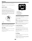
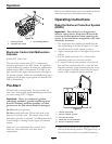
PTO Engagement Switch
Located on right console (see Figure 6).
Switch must be pulled out (up) to engage the blades.
Switch is pushed in to disengage the blades.
The LCD indicator will appear when the PTO switch
is disengaged (see Figure 8).
Low Voltage Indicator
Located on the right console in the message display
(see Figure 6 and Figure 8).
A low voltage condition (less than 12.3 volts) exists
when the LCD indicator appears on the message
display while the engine is running.
If the ignition key is turned to the “ON” position for
a few seconds before cranking the engine, the battery
voltage will display in the area where the hours are
normally displayed.
Note: The indicator normally appears when the
engine is off and the key switch is turned to the
“ON” position.
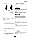
Deck Lift Pedal
Located at the right front corner of the oor pan.
Push the pedal forward with your foot to raise the
cutting deck. Allow the pedal to move rearward to
lower the cutting deck to the cut height that has been
set.
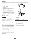
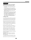
Transport Lock
Located on the height of cut adjustment plates to the
right of the parking brake.
Position in the transport latching position to
automatically latch the cutting deck when raised to
the transport position (see item 1 in Figure 10).
In the non-latching position, the deck will
automatically return to the cutting height when the
pedal is lowered (see item 3 in Figure 10).
23