


Maintenance
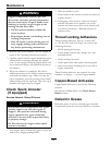
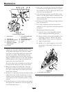
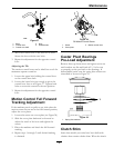
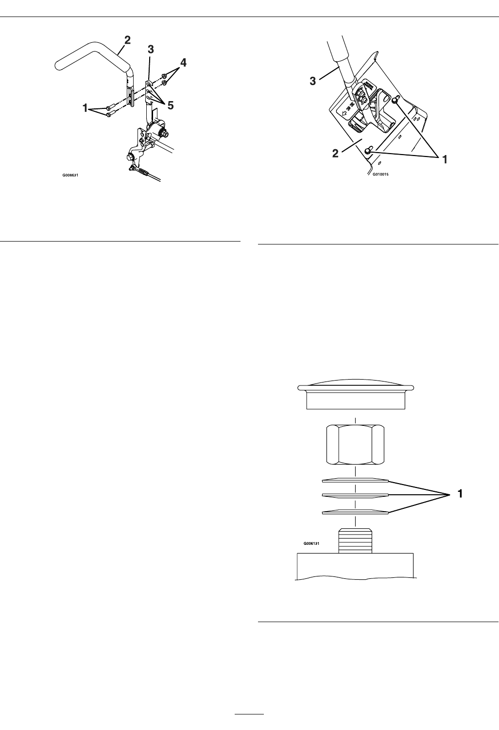
Figure 37
1. Bolts 4. Nuts
2. Control lever 5. Slotted holes
3. Control arm shaft
2. Move the control lever to the next set of holes.
Secure the lever with the two bolts.
3. Repeat the adjustment for the opposite control
lever.
Adjusting the Tilt
The motion control levers can be tilted fore or aft for
maximum operator comfort.
1. Loosen the upper bolt holding the control lever
to the control arm shaft.
2. Loosen the lower bolt just enough to pivot the
control lever fore or aft Figure 37. Tighten both
bolts to secure the control in the new position.
3. Repeat the adjustment for the opposite control
lever.
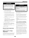
Motion Control Full Forward
Tracking Adjustment
If the machine travels or pulls to one side when the
motion control levers are in the full forward position,
adjust the cover plates.
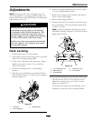
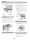
1. Loosen the screws on a cover plate (see Figure 38).
2. Slide the cover plate backward or forward to
adjust the travel of the lever and tighten the
screws.
3. Drive the machine and check the full forward
tracking.
4. Repeat steps 1 through 3 until desired tracking
is obtained.
Figure 38
RH Motion Control Shown
1. Screw
3. Motion control lever
2. Cover plate
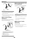
Caster Pivot Bearings
Pre-Load Adjustment
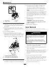
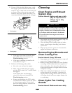
Remove dust cap from caster and tighten nyloc nut
until washers are at and back off 1/4 of a turn
to properly set the pre-load on the bearings. If
disassembled, make sure the spring disc washers are
reinstalled as shown in Figure 39.
Figure 39
1. Spring disc washers
Clutch Shim
Some later model year units have been built with
clutches that contain a brake shim. When the clutch
45