


Maintenance
WARNING
Engine must be running and drive wheels
must be turning so park brake adjustment
can be performed. Contact with moving
parts or hot surfaces may cause personal
injury.
Keep ngers, hands, and clothing clear of
rotating components and hot surfaces.
F. Release the park brake so the handle rests on
the 1/2 x 6 inch rod or bolt.
G. Move the throttle to high idle.
H. Move both motion control levers to the full
forward position and hold for 15 seconds.
I. Move both motion control levers to the full
reverse position and hold for 15 seconds.
J. Turn off the engine and completely release
the park brake by removing the 1/2 x 6 inch
rod or bolt.
K. Allow the hubs to cool until they are cool
enough to safely touch.
L. Rotate the drive wheel release handle to the
“released” position. Refer to the Drive Wheel
Release Valves section in Operation.
M. Readjust both brakes following the procedure
in steps 10 through 14.
18. Rotate the drive wheel release handle to the
“operating” position. Refer to the Drive Wheel
Release Valves section in Operation.
19. Install the rear tires and torque lug nuts to 90-95
ft-lb (122-129 N-m).
20. Remove jack stands.
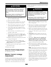
Electric Clutch Adjustment
No adjustment necessary.
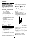
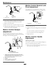
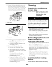
Motion Control Linkage
Adjustment
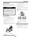
Located on either side of the fuel tank, below the seat
are the pump control linkages. Rotating the pump
linkage with a 1/2 inch wrench allows ne tuning
adjustments so that the machine does not move in
neutral. Any adjustments should be made for neutral
positioning only.
WARNING
Engine must be running and drive
wheels must be turning so motion control
adjustment can be performed. Contact with
moving parts or hot surfaces may cause
personal injury.
Keep ngers, hands, and clothing clear of
rotating components and hot surfaces.
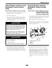
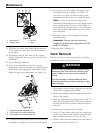
1. Prior to starting the engine, push the deck lift
pedal and remove the height of cut pin. Lower
deck to the ground.
2. Raise the rear of machine up and support with
jack stands (or equivalent support) just high
enough to allow drive wheels to turn freely.
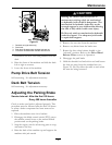
3. Remove the electrical connection from the seat
safety switch, located under the bottom cushion
of the seat. The switch is a part of the seat
assembly.
4. Temporarily install a jumper wire across the
terminals in the connector of the main wiring
harness.
5. Start engine. Brake must be engaged and
motion control levers out to start engine.
Operator does not have to be in the seat
because of the jumper wire being used. Run
engine at full throttle and release brake.
6. Run the unit at least 5 minutes with the drive
levers at full forward speed to bring hydraulic oil
up to operating temperature.
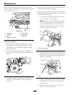
Note: The motion control lever needs to be in
neutral while making any necessary adjustments.
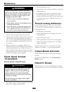
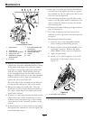
7. Bring the motion control levers into the neutral
position. Adjust pump control rod lengths
by rotating the double nuts on the rod in the
appropriate direction until the wheels slightly
creep in reverse (Figure 34). Move the motion
control levers to the reverse position and while
applying slight pressure to the lever allow the
reverse indicator springs to bring the levers back
to neutral. The wheels must stop turning or
slightly creep in reverse.
43