


Maintenance
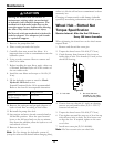
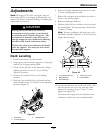
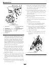
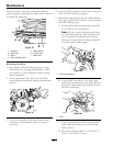
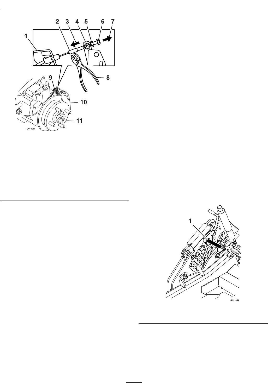
Figure 32
Left Hand Brake Shown
1. Cable anchor
7. Pull cable threaded rod
this direction
2. Threaded rod 8. Hold threaded rod here
3. Push lever this direction
9. Swivel (pivot head)
4. Caliper lever arm 10. Caliper
5. Standard nut (shown
against swivel)
11. Hub
6. Lock nut
10. Remove all slack from cable by pulling on the
caliper lever arm with a medium amount of force.
Using hands and ngers only, push the caliper
lever arm to engage the brake pads on the rotor
until the lever stops. While holding the lever
at the stopped position, use the other hand or
ngers to pull the slack out of the cable threaded
end through the swivel. Spin the standard nut
against the swivel (see Figure 32).
Note the order of the standard nut and lock nut
(no nut on the cable anchor side of the swivel).
11. Release the caliper lever and cable. Turn the
wheel hub by hand in both directions relative to
the caliper; slight drag of the caliper pad on the
wheel hub is desired.
12. If there is no movement between the hub and the
caliper then back off the standard nut one turn
from the swivel and repeat step 11 (drive release
valves must be in the “released” position on the
hydros).
13. If the hub moves very freely relative to the caliper,
then tighten the standard nut one turn against the
swivel and repeat step 11.
14. Once step 11 is achieved, hold the threaded rod
end with a tool and tighten the lock nut against
the standard nut. Do Not allow the cable to turn
when the nuts are tightened.
15. After adjusting the brakes on both sides of the
mower, cycle the brake handle a minimum of six
times to allow the cable to seat into the sheath
and mounting tabs.
16. Readjust both brakes following the procedure in
steps 10 through 14.
17. If a brake component has been removed or
replaced, see the steps below; otherwise proceed
to step 18.
Burnishing the Brake Procedure:
A. Clear the area of any ammable material
before starting the burnishing process.
B. Rotate the drive wheel release handle to the
“operating” position. Refer to the Drive
Wheel Release Valves section in Operation.
C. Apply the park brake.
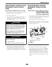
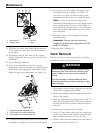
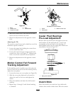
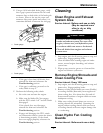
D. Install a 1/2 x 6 inch (approx.) rod or bolt
through the 2 inch height of cut hole (see
Figure 33).
Figure 33
1. 2 inch height of cut location
E. Start the mower while in the operator position.
42