


Operation
Fuel Gauge
Located on the right console in the message display
(see Figure 6 and Figure 9).
The fuel level is shown on a bar display. The indicator
light appears when the fuel level is low (approximately
one gallon remaining in the tank).
Drive Wheel Release Valves
WARNING
Hands may become entangled in the rotating
drive components below the engine deck,
which could result in serious injury or death.
Stop engine, remove key, allow all the moving
parts to stop before accessing the drive wheel
release valves.
WARNING
The engine and hydraulic drive units can
become very hot. Touching a hot engine or
hydraulic drive units can cause severe burns.
Allow the engine and hydraulic drive units to
cool completely before accessing the drive
wheel release valves.
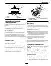
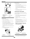
Located on the back of the unitized hydraulic drive
units, below the engine deck.
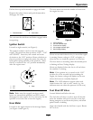
During normal operating conditions, the drive wheel
release valves are positioned horizontally. If the
machine has to be pushed by hand, the valves must
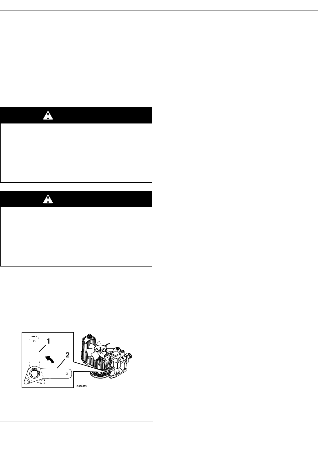
be in the “released” position (see Figure 10).
Figure 10
1. Handle in “released” position
2. Handle in “operating” position
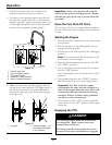
To release the drive system (see item 1 in Figure 10),
rotate the handle 1/4 turn to the vertical position
until it hits against the stop.
To reset the drive system (see item 2 in Figure 10),
rotate the handle 1/4 turn to the horizontal position
until it hits against the stop.
Note: The handle must be horizontal and against
the stop for operation.
Do Not tow machine.
PTO Engagement Switch
Located on right console (see Figure 6).
Switch must be pulled out (up) to engage the blades.
Switch is pushed in to disengage the blades.
The LCD indicator will appear when the PTO switch
is disengaged (see Figure 9).
Low Voltage Indicator
Located on the right console in the message display
(see Figure 6 and Figure 9).
A low voltage condition (less than 12.3 volts) exists
when the LCD indicator appears on the message
display while the engine is running.
If the ignition key is turned to the “ON” position for
a few seconds before cranking the engine, the battery
voltage will display in the area where the hours are
normally displayed.
Note: The indicator normally appears when the
engine is off and the key switch is turned to the
“ON” position.
Coolant Temperature Gauge
(Kawasaki Liquid-Cooled Only)
Located on the right console (see Figure 6).
The coolant temperature gauge monitors the
temperature of the engine coolant. During normal
operating conditions the gauge should be in the green
range. An engine overheating condition is when the
bar display goes to the yellow or red range and an
alarm sounds. Refer to the Warning Buzzer section.
22