


Maintenance
point where the clutch no longer engages consistently,
the shim can be removed to extend the clutch life.
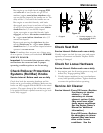
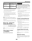
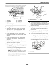
Figure 31
1. Armature 5. Brake spacer
2. Field shell 6. Re-gap shim
3. Rotor 7. Brake pole
4. Brake mounting bolt
Removing the Shim:
1. Stop engine, wait for all moving parts to stop,
and remove key. Engage parking brake. Allow
the machine to cool completely before starting
these instructions.
2. Using a pneumatic line, blow out any debris
from under the brake pole and around the brake
spacers.
3. Check the condition of the wire harness leads,
connectors, and terminals. Clean or repair as
necessary.
4. Verify that 12V is present at the clutch connector
when the PTO switch is engaged.
5. Measure the gap between the rotor and armature.
If the gap is greater than .04 inch (1 mm), proceed
with the following steps:
A. Loosen both brake mounting bolts one-half
to one full turn (see
Figure 32).
Note: Do Not remove the brake pole from
the eld shell/armature. The brake pole has
worn to match the armature and needs to
continue to match after the shim is removed
to ensure proper brake torque.
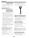
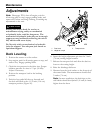
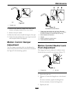
Figure 32
1. Brake mounting bolt
2. Shim
B. Using needle nose pliers, or by hand, take
hold of the tab and remove the shim (Do Not
discard the shim until proper clutch function
has been conrmed).
C. Using a pneumatic line, blow out any debris
from under the brake pole and around the
brake spacers.
D. Re-torque each bolt (M6 x 1) to 10 ft-lb (13
N-m) +/-0.5 ft-lb (0.7 N-m).
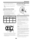
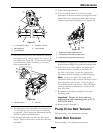
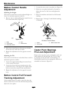
E. Using a 0.010 inch thick feeler gauge, verify
that a gap is present between the rotor and
armature face on both sides of the brake pole
as shown. (Due to the way the rotor and
armature faces wear (peaks and valleys) it is
sometimes difcult to measure the true gap.)
G011733
1
Figure 33
1. Feeler gauge
41