


Maintenance
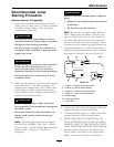
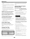
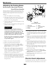
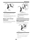
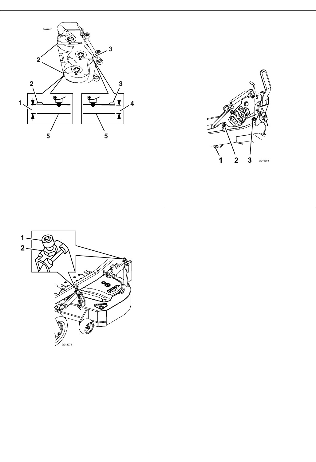
Figure 27
1. 3 1/4 inches (8.3 cm) 4. 3 inches (7.6 cm)
2. Back blade tip
5. Level surface
3. Front blade tip
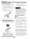
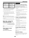
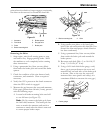
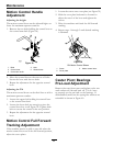
10. Fine tune the front deck lift assembly by turning
the adjuster screw until it reaches the 3 inch (7.6
cm) height (see
Figure 28). To increase the height,
turn the adjuster screw clockwise; to decrease,
turn counterclockwise.
Figure 28
1. Adjuster screw 2. Jam nut
11. The back tips of the side blades should measure
3 1/4 inches (8.3 cm). Fine tune rear adjusters
as required. (The single point adjustment can be
utilized to gain more adjustment.)
12. Re-measure until all four sides are the correct
height. Tighten all the nuts on the deck lift arm
assemblies.
13. Lower discharge deector.
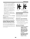
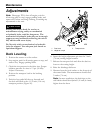
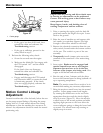
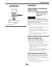
14. If the four deck links do not have enough
adjustment to achieve accurate cut height with the
desired rake, the single point adjustment can be
utilized to gain more adjustment (see Figure 29).
Figure 29
1. Single point height adjustment bolt
2. Front height-of-cut plate mounting bolt
3. Rear height-of-cut plate mounting bolt
15. To adjust the single point system, rst loosen the
front and rear height-of-cut plate mounting bolts.
16. If the deck is too low, tighten the single point
adjustment bolt by rotating it clockwise. If
the deck is too high, loosen the single point
adjustment bolt by rotating it counterclockwise.
Note: Loosen or tighten the single point
adjustment bolt enough to move the height-of-cut
plate mounting bolts at least 1/3 the length of
the available travel in their slots. This will regain
some up and down adjustment on each of the
four deck links.
17. Re-tighten front and rear height-of-cut plate
mounting bolts.
Important: Torque the front and rear
height-of-cut plate mounting bolts to 27-33
ft-lb (37-45 N-m).
18. Repeat steps
9 through 13.
Pump Drive Belt Tension
Self-tensioning - No adjustment necessary.
Deck Belt Tension
Self-tensioning - No adjustment necessary.
39