


Maintenance
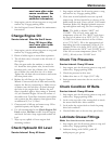
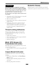
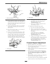
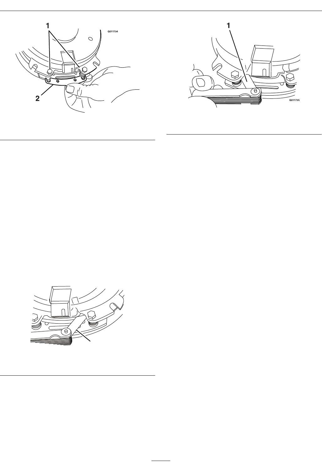
Figure 28
1. Brake mounting bolt
2. Shim
B. Using needle nose pliers, or by hand, take
hold of the tab and remove the shim (Do Not
discard the shim until proper clutch function
has been conrmed).
C. Using a pneumatic line, blow out any debris
from under the brake pole and around the
brake spacers.
D. Re-torque each bolt (M6 x 1) to 10 ft-lb (13
N-m) +/-0.5 ft-lb (0.7 N-m).
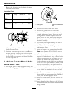
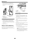
E. Using a 0.010 inch thick feeler gauge, verify
that a gap is present between the rotor and
armature face on both sides of the brake pole
as shown. (Due to the way the rotor and
armature faces wear (peaks and valleys) it is
sometimes difcult to measure the true gap.)
G011733
1
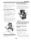
Figure 29
1. Feeler gauge
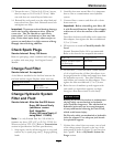
Figure 30
1. Feeler gauge
• If the gap is less than 0.010 inch, then
reinstall the shim and reference the
Troubleshooting section.
• If the gap is sufcient, proceed to the
safety check in step F.
F. Perform the following safety check:
a. Sit on the seat and start the engine.
b. Make sure the blades Do Not engage
with the PTO switch “off ” and the clutch
disengaged.
If the clutch does not disengage,
reinstall the shim and reference the
Troubleshooting section.
c. Engage and disengage the PTO switch
ten consecutive times to ensure the clutch
is functioning properly. If the clutch
does not engage properly, reference the
Troubleshooting section.
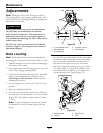
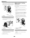
Forward Speed Adjustment
1. Park the machine on a level surface.
2. Shut off engine and wait for all moving parts to
stop. Engage parking brake.
3. Release and lower the rear cushion from the rear
of the machine.
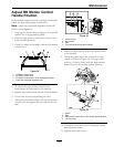
4. Place the front reference/speed control bar in
the maximum forward position. See Adjusting
the Front Reference/Speed Control Bar in
Operation.
5. Push the RH control lever all the way forward to
the front reference/speed control bar.
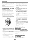
6. Loosen the jam nuts on the turnbuckle on the RH
motion control (as viewed from the rear of the
37