


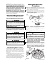
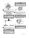
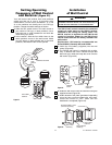
22. 16” Or Optional Longer Downrod Installation: Slide
the decorative scrolls over the 16” downrod to
rest upon the decorative upper housing
(Figure 9) To secure the decorative scrolls to the
downrod, tighten the Philips head screw in the
decorative scroll collar.
DECORATIVE
SCROLLS
16" DOWNROD
DECORATIVE
UPPER HOUSING
DECORATIVE SCROLL
COLLAR
PHILIPS HEAD
SCREW
Figure 9
6
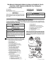
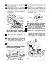
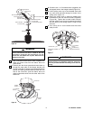
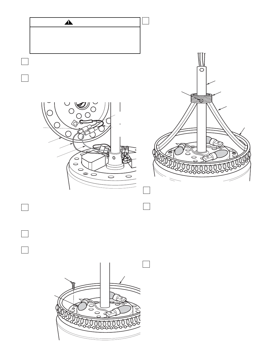
17. Install the setscrew (supplied) in the motor
coupling and tighten using the 5/32” setscrew
wrench (supplied) (Figure 6).
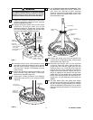
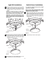
18. Engage the one-pin yellow wire from the motor
housing to the one-pin black wire of the
decorative uplight kit. Engage the one-pin white
wire from the motor housing to the one-pin white
wire of the decorative uplight kit (Figure 7).
19. Carefully tuck all wires and connectors in the
decorative uplight kit assembly before placing
onto the motor housing. Align the four holes in
the decorative uplight kit assembly onto the
motor housing.
20. Secure the decorative uplight kit assembly to the
motor housing using four #8-32 x 10mm pan
head screws (supplied) (Figure 8).
21. Install three 15-watt (minimum) (not supplied)
candelabra light bulbs in the uplight sockets
(Figure 8).
MOTOR HOUSING
YELLOW WIRE
MOTOR HOUSING
WHITE WIRE
DECORATIVE
UPLIGHT KIT
ONE-PIN
CONNECTOR
DECORATIVE
UPLIGHT KIT
WHITE WIRE
DECORATIVE
UPLIGHT KIT
BLACK WIRE
Figure 7
DECORATIVE
UPLIGHT KIT
#8-32 x 10mm
PAN HEAD SCREW (4)
15-WATT (min.)
CANDELABRA
LIGHT BULBS (3)
Figure 8
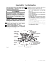
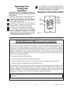
23. Position the ceiling cover over the downrod. Be
sure the cover is oriented correctly, with the large
opening at the top (Figure 10).
24. Reinstall the hanger ball on the downrod
as follows. Route the motor leads through the
hanger ball and slide the hanger ball over the
downrod (Figure 10). Install the pin through the
holes at the top of the downrod and slide the
hanger ball up the downrod, aligning the ball so
the pin is captured in the groove in the top of the
hanger ball. Pull the hanger ball up tight against
the pin and securely tighten the setscrew in the
hanger ball. A loose setscrew could create fan
wobble.
25. The blue, black, white, and yellow leads exiting
the downrod are 80-inches long. Before installing
the fan, measure up approximately 6 to 9-inches
above the ball/downrod assembly. Cut off excess
leads and strip back insulation 1/2-inch from end
of leads.
U.L. Model No.: CF3100U.L. Model No.: CF3100
It is critical that the clevis pin in the motor coupling
is properly installed and the setscrew securely
tightened. Failure to verify that the pin and setscrew
are properly installed could result in the fan falling.
WARNING