


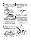
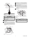
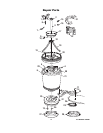
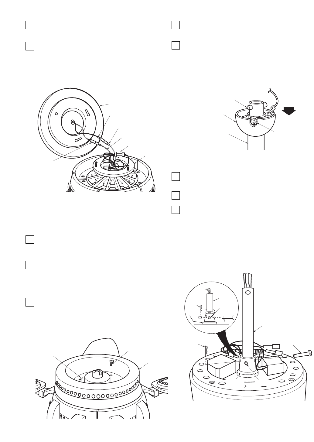
7. Connect the 4-pin connector from the decorative
light kit assembly to the 4-pin connector of the
switch housing (Figure 3).
8. Connect the switch housing blue wire single-pin
connector to the black wire single-pin connector
from the light kit assembly; connect the switch
housing white wire single-pin connector to the
white wire single-pin connector from the light kit
assembly (Figure 3). Be sure all wire connectors
are fully engaged.
CAUTION: Before installing and tightening the
screws, be sure there are no wires pinched
between the switch housing and the light kit
assembly.
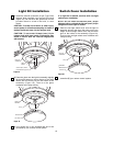
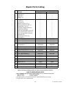
9. Make sure all wires, single-pin and 4-pin
connectors are inside the switch housing, then
position the light kit assembly on the switch
housing so that the holes line up.
10. Attach the light kit assembly to the switch
housing using the three #8-32 x 10mm pan head
screws (supplied). Do not tighten screws at this
time. Position the light kit assembly onto the
switch housing, making sure all wires are not
pinched (Figure 4).
11. Rotate the light kit assembly clockwise to engage
the keyhole slots. Secure all three screws at this
time (Figure 4).
NOTE: Be sure wires and connectors are not
pinched under the decorative light kit assembly
before securing the light kit assembly.
5
SWITCH HOUSING BLUE
WIRE CONNECTOR
LIGHT KIT ASSEMBLY
BLACK WIRE CONNECTOR
LIGHT KIT ASSEMBLY
WHITE WIRE
CONNECTOR
SWITCH HOUSING WHITE
WIRE CONNECTOR
LIGHT KIT ASSEMBLY
SWITCH
HOUSING
4-PIN CONNECTORS
Figure 3
#8-32 x 10mm PAN
HEAD SCREWS (3)
LIGHT KIT
ASSEMBLY
KEYHOLE SLOT (2)
Figure 4
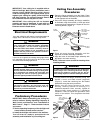
12. Carefully turn over the partially assembled ceiling
fan and place onto the flat surface of the
styrofoam.
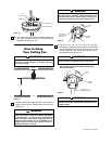
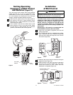
13. Obtain the hanger ball/downrod assembly and
remove the hanger ball by loosening the
setscrew in the hanger ball until the ball falls
freely down the downrod (Figure 5). Remove the
pin from the downrod, then remove the hanger
ball. Retain the pin and hanger ball for
reinstallation in Step 24.
NOTE: The 16” downrod furnished with the
ceiling fan provides the minimum recommended
floor-to-fan blade clearance for a 9-foot ceiling.
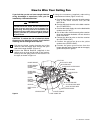
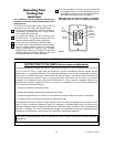
14. Separate, untwist and unkink the black, white and
blue motor wires and the yellow uplight lead.
Route these wires through the downrod.
15. Slide the downrod down the wires and seat the
downrod in the motor coupling (Figure 6).
16. Align the clevis pin holes in the downrod with the
holes in the motor coupling. Install the clevis pin
and secure with the hairpin clip (Figure 6). The
clevis pin must go through the holes in the motor
coupling and the holes in the downrod. Push the
straight leg of the hairpin clip through the hole
near the end of the clevis pin until the curved
portion of the hairpin clip snaps around the clevis
pin. The hairpin clip must be properly installed to
prevent the clevis pin from working loose.
U.L. Model No.: CF3100
HANGER BALL
PIN
DOWNROD
SETSCREW
Figure 5
DOWNROD
CLEVIS PIN
HAIRPIN
CLIP
SETSCREW
CLEVIS PIN
MOTOR
COUPLING
DOWNROD
HAIRPIN
CLIP
MOTOR
COUPLING
SETSCREW
Figure 6