


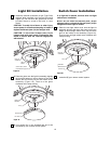
LIGHT KIT
ASSEMBLY
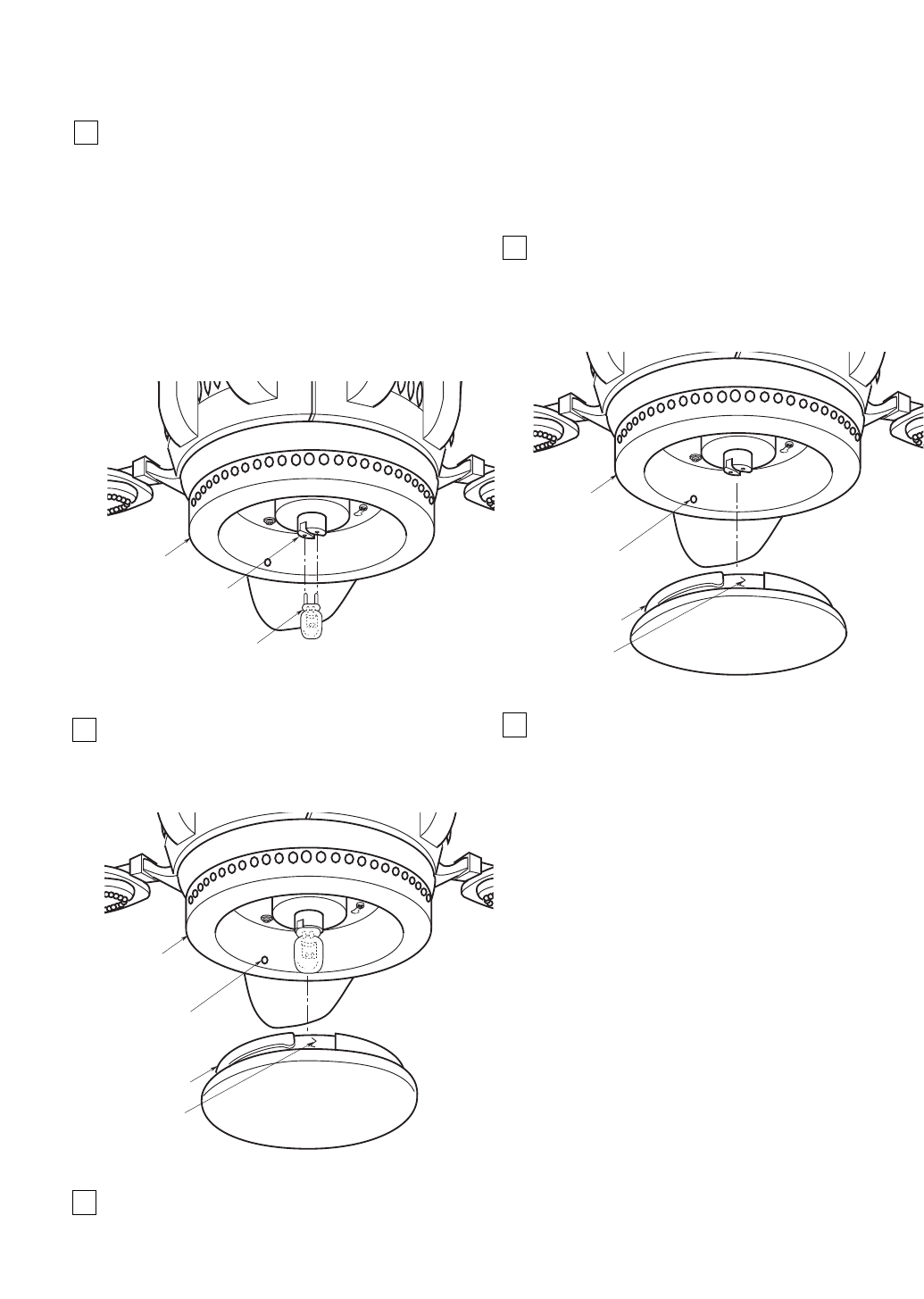
LIGHT KIT
SOCKET
50-WATT (Max.) BI-PIN
HALOGEN BULB (Type GY8)
10
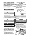
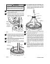
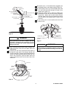
2. Place the glass onto the light kit assembly aligning
the three flat areas on the top flange of the glass
shade with the three pins on the inside of the
assembly (Figure 19). Then turn the glass
clockwise until it stops turning.
3. Your ceiling fan is now installed and wire to be
controlled by your remove control system.
Figure 18
LIGHT KIT
ASSEMBLY
PIN (3)
FLAT AREA (3)
GLASS SHADE
Figure 19
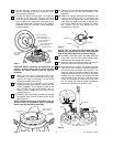
1. Install the 50-watt (maximum) bi-pin (Type GY8)
halogen bulb (supplied) into the light kit socket
(Figure 18). Do not touch the glass bulb; use the
porcelain base to screw in the bulb, or wear
gloves.
CAUTION: To avoid risk of burns or other injury,
assure power is off before attempting to install or
replace the 50-watt (max.) bi-pin halogen bulb.
CAUTION: To not touch 50-watt (max.) bi-pin
halogen bulb with bare hands. Fingerprints may
result in shorter bulb life. Remove fingerprints
with alcohol.
Light Kit Installation
NOTE: Do not install the 50-watt (max.) bi-pin
halogen bulb or unhook the 50-watt (max.) bi-pin
halogen bulb from light kit socket.
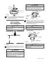
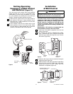
1. Place the non-light switch cover onto the light kit
assembly aligning the three flat areas on the top
flange of the non-light switch cover with the three
pins on the inside of the assembly (Figure 20).
Then turn the non-light switch cover clockwise until
it stops turning.
2. Your ceiling fan is now installed and wire to be
controlled by your remove control system.
LIGHT KIT
ASSEMBLY
PIN (3)
FLAT AREA (3)
SWITCH COVER
Figure 20
If no light kit is desired, continue with non-light
switch cover installation.
Switch Cover Installation
NON-LIGHT
SWITCH COVER