


12
Italiano
ASSEMBLAGGIO
English
ASSEMBLY
1 A 1 B 2 3 4
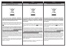
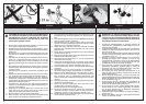
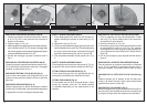
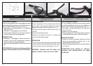
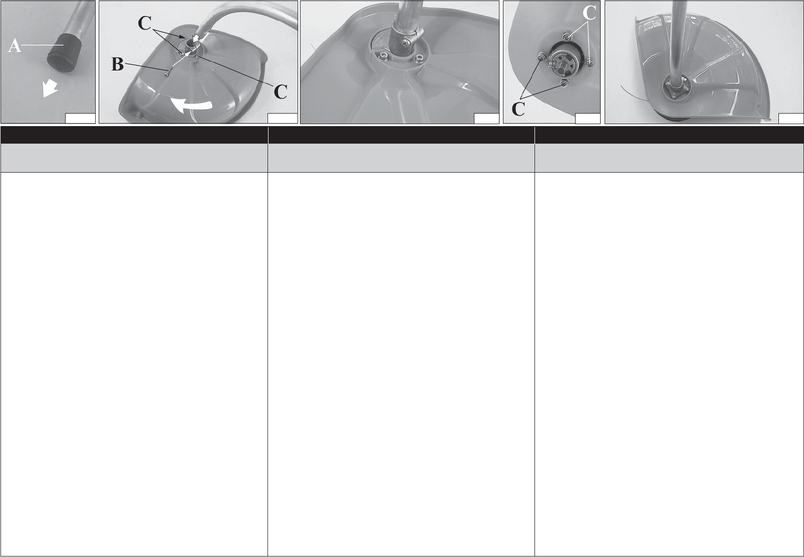
MONTAGGIO PROTEZIONE SICUREZZA 600 W
1. Fissare la protezione al tubo di trasmissione tramite
le viti (
C, Fig. 1B
), in una posizione che permetta di
lavorare in sicurezza.
2. Togliere il tappo (A, Fig. 1A).
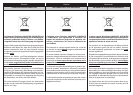
3. Infi lare il gruppo mozzo-testina-protezione nel tubo di trasmis-
sione e serrare la vite (B, Fig. 1B); durante il serraggio della
vite, tenere il gruppo mozzo-protezione leggermente spinto
nel senso indicato dalla freccia in Fig. 1B.
4. Alla fi ne del montaggio il gruppo si presenta come in
Fig. 2.
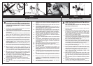
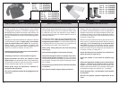
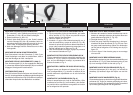
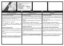
MONTAGGIO PROTEZIONE SICUREZZA 850 W
Fissare la protezione al tubo di trasmissione tramite le viti (C,
Fig. 3); posizionare la protezione in modo che, a montaggio
avvenuto, si presenti come in Fig. 4.
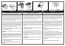
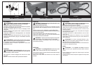
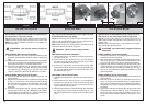
MONTAGGIO TESTINA A FILI DI NYLON (Fig. 5)
Inserire il perno fermo testina (H) nell'apposito foro (L) ed
avvitare in senso antiorario la testina (N) con la sola forza
delle mani.
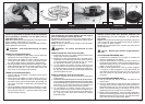
MONTAGGIO IMPUGNATURA (Fig. 6)
Montare l'impugnatura sul tubo di trasmissione e fi ssarla
tramite viti (A), rondelle e dadi. La posizione dell'impugnatura
è registrabile in funzione all'esigenza dell'operatore.
ASSEMBLAGE
SAFETY GUARD ASSEMBLY 600 W
1. Fit the blade guard to the shaft arm with screws in a
position allowing the operator to work safely (
C, Fig.
1B
).
2. Remove the cap (A, Fig. 1A).
3. Fit the pre-assembled hub-head-guard onto the drive
shaft and tighten the screw (B, Fig. 1B); while tightening
the screw, push a little the pre-assembled hub-guard
toward the side shown by the arrow in picture 1B.
4. The completed assembly should appear as in Fig.
2.
SAFETY GUARD ASSEMBLY 850 W
Fit the blade guard to the saft arm with screws (C, Fig. 3);
the guard in the correct position should look like Fig. 4.
FITTING THE NYLON LINE HEAD (Fig. 5)
Put the head fi xing pin (H) in the appropriate hole (L)
and tighten the head (N) anti-clockwise by hand.
FITTING THE HANDLE (Fig. 6)
Fit the handle onto the shaft arm and secure it using
screws (A), washers, and nuts. The handle position
is calculated depending on the requirements of the
operator.
MONTAGE DE LA PROTECTION SECURITÉ 600W
1. Fixer la protection au tuyau de transmission à l'aide
des vis (
C, Fig. 1B
) en position telle à vous permettre
de travailler en toute sécurité.
2. Enlever le bouchon (A, Fig. 1A).
3. Aboucher le group moyen-tête-protection dans le tube
de transmission et serrer la vis (B, Fig. 1B); pendant
le serrage de la vis, tenir le group moyen-protection un
peu poussé dans le sens indiqué par la fl èche dans la
fi gure 1B.
4. À la fi n du montage le group apparâit comme dans la
fi gure 2.
MONTAGE DE LA PROTECTION SECURITÉ 850 W
Fixer la protection au tuyau de transmission à l’aide des
vis (C, Fig. 3); positioner la protection de façon pue, à
montage completé, se presente comme dans la fi gure
4.
MONTAGE DE LA TETE AUX FILS DE NYLON (Fig.
5)
Enfi lez le goujon qui va bloquer la tête (H) dans son
orifi ce (L) et vissez à la main, dans le sens contraire des
aiguilles d'une montre, la tête (N).
MONTAGE DE LA POIGNEE (Fig. 6)
Montez la poignée sur le tuyau de transmission et fi xez-la
avec les vis (A), les rondelles et les écrous. La position de
la poignée se règle selon les exigences de l'opérateur.
Français