


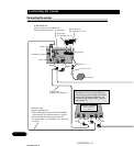
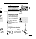
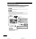
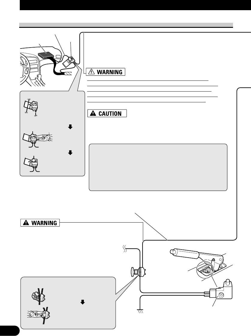
Pink (CAR SPEED SIGNAL INPUT)
The mobile navigation system is connected here to detect the distance
the vehicle travels. Always connect the vehicle’s speed detection
circuit or the ND-PG1 speed pulse generator, sold separately. Failure
to make this connection will increase errors in the location display.
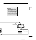
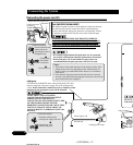
IMPROPER CONNECTION MAY RESULT IN SERIOUS
DAMAGE OR INJURY INCLUDING ELECTRICAL SHOCK,
AND INTERFERENCE WITH THE OPERATION OF THE
VEHICLE’S ANTILOCK BRAKING SYSTEM, AUTOMATIC
TRANSMISSION AND SPEEDOMETER INDICATION.
LIGHT GREEN LEAD AT POWER
CONNECTOR IS DESIGNED TO DETECT
PARKED STATUS AND MUST BE
CONNECTED TO THE POWER SUPPLY SIDE
OF THE PARKING BRAKE SWITCH.
IMPROPER CONNECTION OR USE OF THIS
LEAD MAY VIOLATE APPLICABLE LAW
AND MAY RESULT IN SERIOUS INJURY OR
DAMAGE.
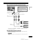
Light green
Used to detect the ON/OFF status of the parking brake. This lead
must be connected to the power supply side of the parking brake
switch. If this connection is made incorrectly or omitted, certain
functions of your navigation system will be unusable.
• It is strongly suggested that the speed pulse wire be connected
for accuracy of navigation and better performance of interlock.
• If the speed pulse wire is unavailable for some reason, it is
recommended that the pulse generator (ND-PG1) be used.
Notes:
• The position of the speed detection circuit and the position of the
parking brake switch vary depending on the vehicle model. For
details, consult your authorized Pioneer dealer or an installation
professional.
• Even when the light green lead and the pink lead are connected
correctly, a message indicating improper connection is shown until
sensor initialization has completed.
Be sure to
lead could
11
Connecting the System
ENG/MASTER 96
<CRD3983A> 12
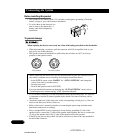
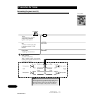
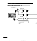
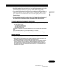
Connecting the power cord (2)
Connection method
Clamp the parking brake
switch power supply side lead.
Clamp firmly with
needle-nosed pliers.
Power supply side
Ground side
Parking brake switch
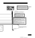
Speed detection circuit lead
Vehicle injection
computer
Connector
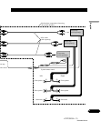
Pass the extension cord
and the lead for the
speed detection circuit
through this hole.
Clamp firmly
with needle-
nosed pliers.
Close the cover.
Connection method