


28 se c t i O n 6— Ma i n t e n a n c e & ad j u s t M e n t s
The final adjustment would be to set the Trailing Link by 8.
adjusting the jam nuts on the threaded link. Loosen the
jam nuts and tighten the inner nut to achieve the correct
In many cases it will be necessary to adjust deck height
using both eyebolt adjustments and pitch adjustment
to achieve the correct blade-to-ground heights. If you
remember that the front right blade tip adjustment is fixed
and you level to that height, adjusting the decks will be
simplified.
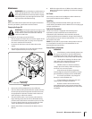
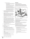
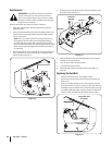
Adjusting the Belt Tension
To tighten or loosen the tension on the belt, tighten or loosen
the jam nuts on the U-rod, see Fig. 6-7, until a ten-pound pull
with a spring scale deflects the belt about ⁄
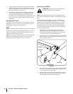
Brakes
NOTE: The parking brakes normally do not need to be adjusted.
To adjust either brake individually, loosen the jam nuts on the
cable near the brake arm on the transaxle. Adjust the nuts so
that the brake cable becomes shorter.
Repair: The mower is equipped with internal gear/pawl brakes
and will not normally require maintenance. If they are not
working properly, please contact your service center.
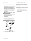
Adjusting the Gauge Wheels
WARNING! Keep hands and feet away from the
discharge opening of the cutting deck.
NOTE: The deck gauge wheels are an anti-scalp feature of the
deck and are not designed to support the weight of the cutting
deck.
gauge wheel position should be approximately ⁄ to ⁄ above
the ground when the deck is set in the desired height setting.
Using the lift pedal, set the deck in the desired height setting,
then check the gauge wheel distance from the ground below. If
necessary, adjust as follows:
Visually check the distance between the front gauge
wheels and the ground. If the gauge wheels are near or
touching the ground, they should be raised. If more than
⁄
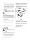
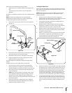
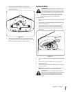
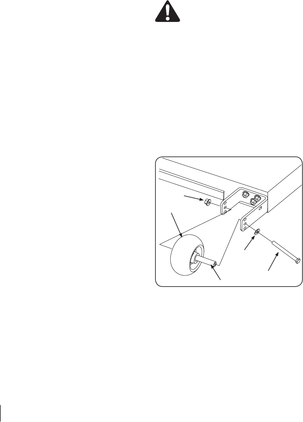
Remove the lock nut securing one of the front gauge wheel 2.
shoulder screws to the deck. Remove the gauge wheel and
hex screw. Refer to Fig. 6-7.
Insert the hex screw into the one of three index holes in the
front gauge wheel bracket that will give the gauge wheel a
⁄ to ⁄
Note the index hole of the just adjusted wheel, and adjust 4.
the other gauge wheels into the respective index holes of
the other gauge wheel brackets on the deck.
Lock Nut
Hex Screw
Deck Wheel
Washer
Wheel Spacer
Figure 6-7