


27se c t i O n 6 — Ma i n t e n a n c e & ad j u s t M e n t s
Adjustment lever is located under the front edge of the
seat.
The seat has five inches of front-to-rear adjustment
available.
Check factory settings of control levers for the conditions listed
above.
NOTE: If control lever adjustments are required, height
adjustments should be made prior to angular adjustments.
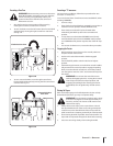
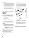
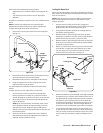
To adjust the height of the drive control levers:
Remove the nuts from the control lever mounting bolts.
Remove the bolts and control lever and reposition to the 2.
second set of holes in the mounting block.
If angular adjustments are also required, nuts can be 4.
tightened until snug at this point.
The same adjustments should be made to both sides of the
mower.
To adjust the front-to-rear angle of the control levers:
Loosen the nuts on the control lever mounting bolts,
leaving the bottom one fairly snug. The bottom hole is
slotted, allowing the control lever to pivot on the top bolt.
Move control lever to the desired angle and tighten the 2.
NOTE: In the neutral position, the handles of the control
levers should be aligned with approximately a one inch
gap between the tips. Widen the gap by adding shim
washers to the top mounting bolt between the lap bar and
the mounting block.
Check the results of any adjustments to the conditions
described above. Repeat any adjustment procedures as
required until all conditions are met.
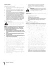
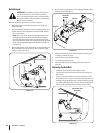
Leveling the Mower Deck
When correctly adjusted the mower deck should be level side to
side, and the front of the deck should be approximately ⁄
than the rear of deck.
NOTE:
inflation pressures.
parking brake, shut off the engine, remove the key from the
ignition switch, disconnect the spark plug wires.
Using the deck lift pedal, position the mowing deck into 2.
the highest mowing position.
Measure blade-to-ground height at the front tip of the
right blade. To obtain an accurate measure, align blades in
parallel with mower centerline, (i.e. front to back).
Measure blade-to-ground height at the front tip of the left 4.
arranged in proper position.
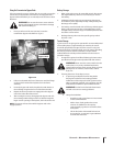
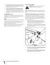
With a 5. ⁄
of the lift link. To adjust the side of the deck up or down
turn the upper jam nut clockwise (to raise) or counter
Measure the blade-to-ground height at the right rear blade 6.
tip. Again be sure to measure at the blade tip at the rear of
the right blade when aligned along the mower centerline.
The blade-to-ground height at the rear of the blade tip
should be approximately ⁄
is referred to as blade pitch. The same height difference
should be true for the left blade, measured front and back.
To change the pitch (front to rear), loosen the lower nuts 7.
on the rear Lift Links. With a few turns, adjust clockwise (to
raise) or counter clockwise (to lower) the upper nuts of the
nuts.
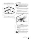
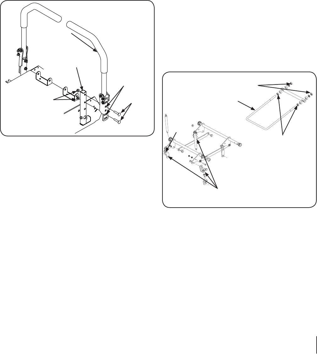
Control Lever
Pivot Bracket
Flange
Lock Nuts
Height
Adjustment
Holes
Carriage
Bolts
Figure 6-5
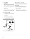
Adjustable
Lift Link
Right Side
Jam
Nut
Inner Jam
Nuts
Front of
Unit
Outer Jam Nuts
Trailing Link
Left Side
Figure 6-6