


10 se c t i O n 2— as s e M b l y & se t-up
Connecting the Battery Cables
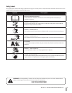
CALIFORNIA PROPOSITION 65 WARNING!
contain lead and lead compounds, chemicals known
reproductive harm. Wash hands after handling.
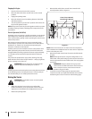
CAUTION: When attaching battery cables, always
For shipping reasons, both battery cables on your equipment
may have been left disconnected from the terminals at the
factory. To connect the battery cables, proceed as follows:
NOTE:
negative battery terminal is marked Neg. (–).
NOTE: If the positive battery cable is already attached, skip
ahead to step 2.
Remove the plastic cover, if present, from the positive
battery terminal and attach the red cable to the positive
Remove the plastic cover, if present, from the negative 2.
battery terminal and attach the black cable to the negative
terminal to help protect it from corrosion.
NOTE: If the battery is put into service after the date shown
on top/side of battery, charge the battery as instructed in the
the tractor.
4.
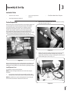
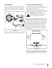
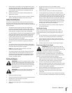
NOTE: Insert self-tapping screw through hole in lanyard
and down into the same hole that it was removed from.
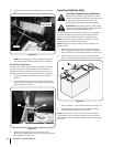
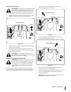
Position Drive Control levers
The drive control levers of the tractor are lowered for shipping
purposes. Using the hardware found in the manual bag, the
control levers must be repositioned to operate the tractor. To
reposition the control levers for operation, proceed as follows:
Lift and swing the control levers up into the operating
position.
From the outside, insert the bolts through the hourglass 2.
Maintenance & Adjustments section for instructions on the
final adjustment of the levers.
Existing Self-
tapping Screw
Lanyard
Figure 3-4
Hourglass
Spacer
Nut
Bolt
Figure 3-6
Figure 3-5