


21se c t i O n 6 — Ma i n t e n a n c e & ad j u s t M e n t s
Adjustments
WARNING! Never attempt to make any
adjustments while the engine is running, except
where specified in the operator’s manual.
Disconnect spark plug wire(s) before performing any
adjustments, repairs or maintenance.
Steering and Transmission Linkage
The steering tie rod and drag links and the related transmission
linkage are set at the factory and should not require further
adjustment. Because of the complex adjustment procedure, the
steering and transmission linkage should only be serviced or
adjusted by a qualified mechanic. If you experience problems
with steering, or with the hydro drive transmissions, contact your
nearest Cub Cadet dealer to have the tractor inspected.
Adjusting the Seat
WARNING! After adjusting the seat or before
driving the tractor, make sure that the seat
adjustment lever is engaged in the seat index plate
and that the seat will not move. Do not adjust the
seat while the tractor is being driven. Adjusting the
seat while the tractor is moving could cause the
operator to lose control of the tractor.
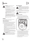
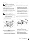
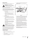
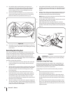
While sitting in the seat, grasp the seat adjustment lever 1.
on the left side of the seat and pull it upward to disengage
from the seat index plate. See Fig. 6-4.
Slide the seat to the desired position. See Fig. 6-4.2.
Once the desired position is reached, release the seat lever. 3.
Slide the seat slightly fore and aft as necessary to engage
the seat lever into one of the eight adjustment positions in
the index plate. Make certain the seat is locked in position.
Side to Side Leveling the Deck
NOTE: Check the tractor’s tire pressure before performing any
deck leveling adjustments. Refer to “Tires” earlier in this section
for information regarding tire pressure.
If the cutting deck appears to be mowing unevenly, a side to side
adjustment can be performed. Adjust if necessary as follows:
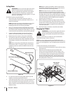
With the tractor parked on a firm, level surface, move the 1.
deck to the mid height position (third or fourth notch)
using the deck lift lever. Rotate the left blade so that it is
perpendicular to the tractor frame. Measure and record
the distance from the outside of the left blade tip to the
ground.
Moving to the other side of the tractor, rotate the right 2.
blade so that it is perpendicular to the tractor frame,
and measure the distance from its outer blade tip to the
ground.
Both measurements taken should be equal. If they’re not, 3.
note whether the left side of the deck is lower or higher
and proceed to the next step.
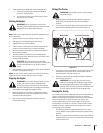
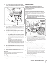
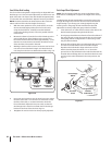
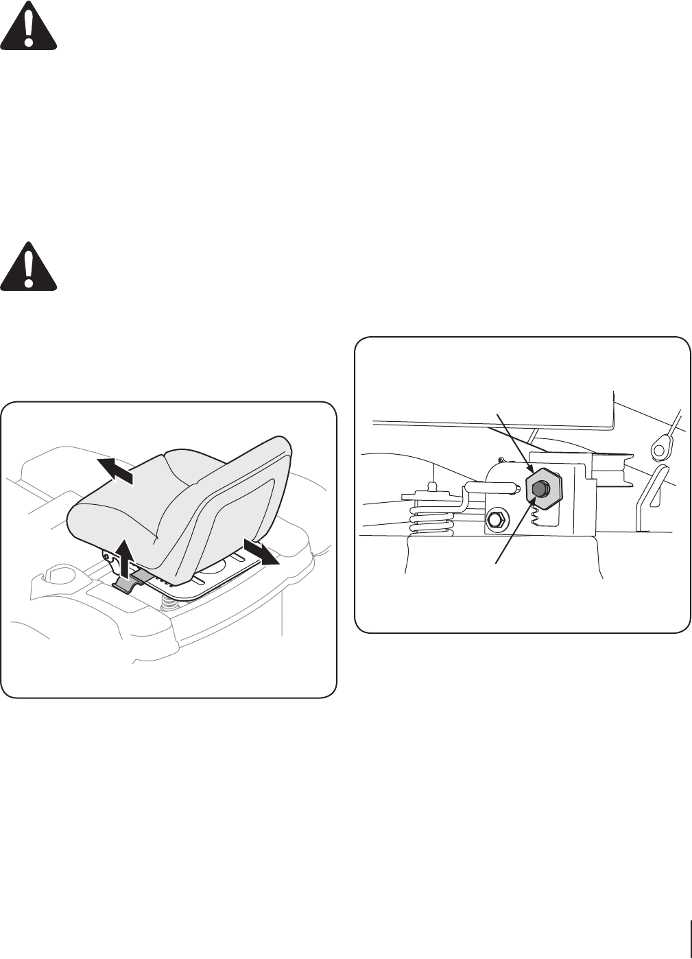
Working from the left side of the tractor, loosen, but do 4.
not remove, the hex cap screw in the left deck adjustment
bracket. See Fig. 6-5.
To even the deck turn the adjustment gear, located 5.
immediately behind the hex cap screw, clockwise
(rearward) to lower the left side of the deck. Turn the gear
counter-clockwise (toward front) to raise the left side of the
deck. See Fig. 6-5.
The deck is properly leveled when both blade tip 6.
measurements, as described earlier, are equal.
Retighten the hex cap screw in the left deck adjustment 7.
bracket when proper adjustment is achieved.
Figure 6-4
Adjustment Gear
Hex Cap Screw
Figure 6-5