


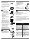

1. Stop the engine and allow oil to drain into the crankcase.
2.
Place the unit on a flat, level surface to get a proper oil level reading.
3. Keep dirt, grass clippings and other debris out of the
engine. Clean the area around the oil fill plug/dipstick
before removing it.
4. Remove the oil fill plug/dipstick and wipe off oil. Reinsert it
all the way back in.
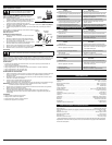
5. Remove the oil fill plug/dipstick and check the oil level. Oil
should be up to the top of the dipstick (Fig. 22).
6. If the level is low, add a small amount of oil to the oil fill hole
and recheck (Fig. 23). Repeat this procedure until the oil
level reaches the top of the dipstick.
NOTE: Do not overfill the unit.
NOTE:
Make sure the O-ring is in place on the oil fill plug/dipstick
when checking and changing the oil (Fig. 22).
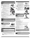
CHANGING THE OIL
For a new engine, change the oil after the first 10 hours of
operation. Change the oil while the engine is still warm. The oil will
flow freely and carry away more impurities.
1. Unplug spark plug boot to prevent accidental starting.
2. Remove the oil fill plug/dipstick.
3. Pour the oil out of the oil fill hole and into a container by
tipping the unit to a vertical position (Fig. 24). Allow ample
time for complete drainage.
4. Wipe up any oil residue on the unit and clean up any oil that
may have spilled. Dispose of the oil according to Federal,
State and local regulations.
5. Refill the crankcase with 3.04 fluid ounce (90 ml) of SAE 30
SF, SG, SH oil.
NOTE: Use the bottle and spout saved from initial use to
measure the correct amount of oil. The top of the
label on the bottle measures approximately 3.4
ounces (100 ml) (Fig. 25). Check the level with the
dipstick. If the level is low, add a small amount of oil
and recheck. Do not overfill (Fig. 25).
6. Replace the oil fill plug/dipstick.
7. Reconnect the spark plug boot.
AIR FILTER MAINTENANCE
Cleaning the Air Filter
Clean and re-oil the air filter every 10 hours of operation. It is an
important item to maintain. Failure to maintain your air filter
properly can result in poor performance or can cause permanent
damage to your engine.
1. Open the air filter cover. Push the tab on the left side of the
cover inward. Then pull the air filter cover out and to the
right (Fig. 26).
NOTE: It may be necessary to remove the fuel cap to
completely remove the air filter cover.
2. Remove the air filter (Fig. 26).
3. Wash the filter in detergent and water (Fig. 27). Rinse the
filter thoroughly and allow it to dry.
4. Apply enough clean SAE 30 motor oil to lightly coat the
filter (Fig. 28).
5. Squeeze the filter to spread and remove excess oil (Fig. 29).
6. Replace the filter (Fig. 30).
NOTE: If the unit is operated without the air filter, you will
VOID the warranty.
7. Reinstall the air filter cover. Position the hooks on the right
side of the air filter cover into the slots at the right side of
the back plate (Fig. 31, no.1).
8. Swing the cover to the left until the tab on the air filter cover
snaps into place in the slot on the back plate (Fig. 31, no. 2).
CARBURETOR ADJUSTMENT
The idle speed of the engine is adjustable. An idle adjustment screw
is reached though a hole in the top of the engine cover (Fig. 32).
NOTE: Careless adjustments can seriously damage your
unit. An authorized service dealer should make
carburetor adjustments.
Check Fuel
Old fuel is usually the reason for improper unit performance. Drain
and refill the tank with fresh fuel prior to making any adjustments.
Refer to Oil and Fuel Information.
Clean Air Filter
The condition of the air filter is important to the operation of the
unit. A dirty air filter will restrict air flow. This is often mistaken for
an out of adjustment carburetor. Check the condition of the air
filter before adjusting the idle speed screw. Refer to Air Filter
Maintenance.
Adjust Idle Speed Screw
5
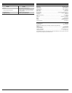
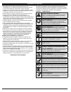
FREQUENCY MAINTENANCE REQUIRED SEE
Before starting engine Fill fuel tank with fresh fuel
Check oil
p. 4
p. 5
Every 10 hours Clean and re-oil air filter p. 5
1st change at 10 hours
2nd change at 25 hours
Every 25 hours after
Change oil
Change oil
Clean spark arrestor
p. 5
p. 5
p. 6
10 hours on new engine
Every 25 hours
Every 25 hours
Check rocker arm to valve clearance and adjust
Check rocker arm to valve clearance and adjust
Check spark plug condition and gap
p. 6
p. 6
p. 6
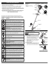
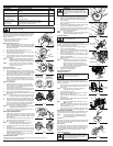
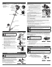
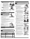
LINE INSTALLATION
This section covers both SplitLine™ and standard single line installation.
Always use original equipment manufacturer 0.095 in (2.41 mm)
replacement line. Line other than the specified may make the
engine overheat or fail.
There are two methods to replace the trimming line:
• Wind the inner reel with new line
• Install a prewound inner reel
Winding the Existing Inner Reel
1. Hold the outer spool with one hand and unscrew the Bump
Knob™ counterclockwise (Fig. 13). Inspect the bolt inside
the Bump Knob to make sure it moves freely. Replace the
Bump Knob if damaged.
2. Remove the inner reel from the outer spool (Fig. 14).
3. R
emove spring from the inner reel (Fig. 14).
4. Use a clean cloth to clean the the inner reel, spring, shaft,
and inner surface of the outer spool.
5. Check the indexing teeth on the inner reel and outer spool
for wear (Fig. 15). If necessary, remove burrs or replace the
reel and spool.
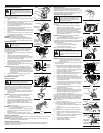
NOTE: SplitLine™ can only be used with the inner reel with the
slotted holes. Single line can be used on either type of
inner reel. Use Figure 16 to identify the inner reel you have.
NOTE: Always use the correct line length when installing
trimming line on the unit. The line may not release
properly if the line is too long.
Single Line Installation
Go To Step 8 for SplitLine™ Installation
6. Take approximately 20 feet (6 m) of new trimming line, loop it
into two equal lengths. Insert each end of the line through one
of the two holes in the inner reel (Fig. 17). Pull the line through
the inner reel so that the loop is as small as possible.
7. Wind the lines in tight even layers, onto the reel (Fig. 18).
Wind the line in the direction indicated on the inner reel.
Place your index finger between the two lines to stop the
lines from overlapping. Do not overlap the ends of the line.
Proceed to step 11.
SplitLine™ Installation
8. Take approximately 10 feet (3 m) of new trimming line.
Insert one end of the line through one of the two holes in
the inner reel (Fig. 19). Pull the line through the inner reel
until only about 4 inches is left out.
9.
Insert the end of the line into the open hole in the inner reel and
pull the line tight to make the loop as small as possible (Fig. 19).
10. Before winding, split the line back about 6 inches.
11. Wind the line in tight even layers in the direction indicated on
the inner reel.
NOTE: Failure to wind the line in the direction indicated will
cause the cutting attachment to operate incorrectly.
12.
Insert the ends of the line into the two holding slots (Fig. 20).
13.
Insert the ends of the line through the eyelets in the outer spool
and place inner reel with spring inside the outer spool (Fig. 21).
Push the inner reel and outer spool together. While holding the
inner reel and outer spool, grasp the ends and pull firmly to
release the line from the holding slots in the reel.
NOTE: The spring must be assembled on the inner reel before
reassembling the cutting attachment.
14. Hold the inner reel in place and install the bump knob by
turning clockwise. Tighten securely.
INSTALLING A PREWOUND REEL
1. Hold the outer spool with one hand and unscrew the bump
knob counterclockwise (Fig. 13). Inspect the bolt inside the
bump knob to make sure it moves freely. Replace the bump
knob if damaged.
2. Remove the old inner reel from the outer spool (Fig. 14).
3. Remove the spring from the old inner reel (Fig. 14).
4. Place the spring in the new inner reel.
NOTE: The spring must be assembled on the inner reel
before reassembling the cutting attachment.
5. Insert the ends of the line through the eyelets in the outer
spool (Fig. 21).
6. Place the new inner reel inside the outer spool. Push the inner
reel and outer spool together. While holding the inner reel and
outer spool, grasp the ends and pull firmly to release the line
from the holding slots in the spool.
7. Hold the inner reel in place and install the bump knob by
turning clockwise. Tighten securely.
CHECKING THE OIL LEVEL
The importance of checking and maintaining the proper oil level in the crankcase cannot be
overemphasized. Check oil before each use:
MAINTENANCE AND REPAIR INSTRUCTIONS
Bolt
Bump Knob™
Fig. 13
Outer Spool
Spring
Inner Reel
Fig. 14
For Use with
Single Line ONLY
Slotted
Holes
Fig. 16
Indexing Teeth
Fig. 15
Loop
Fig. 17
Fig. 18
Loop
Fig. 19
Index Teeth
Fig. 20
Spring
Fig. 21
For Use with
Splitline™ or
Single Line ONLY
WARNING:
N
ever use metal-reinforced line, wire, chain or rope. These can break off and
become dangerous projectiles.
Eyelets
Full
Fig. 22
O-Ring Oil Fill Plug/Dipstick
Oil Fill Hole
Fig. 23
Top of
Dipstick
Add 1.4-1.5 Oz.
(41-44 ml)
Fig. 24
Fill Level
Fig. 25
Oil Fill
Plug/Dipstick
WARNING:
To prevent extensive engine wear
and damage to the unit, always maintain the
proper oil level in the crankcase. Never operate
the unit with the oil level below the bottom of the
dipstick.
CAUTION:
Wear gloves to prevent injury
when handling the unit.
WARNING:
To avoid serious personal injury,
always turn the unit off and allow it to cool
before you clean or service it.
Tab
Fig. 26
Air Filter Air Filter Cover
Fig. 27
Fig. 28
WARNING:
The cutting attachment will spin
during idle speed adjustments. Wear protective
clothing and observe all safety instructions to
prevent serious personal injury.