


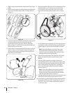
Figure 6-5
Auger Shaft
At least once a season, one at a time, remove the shear pins from
the auger shaft. Spray lubricant inside the hub of each auger
spiral assembly and around the spacers on the auger shaft.
Grease fittings can also be found at each end of the auger shaft.
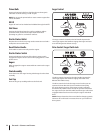
Lubricate flange bearings found at each end of the shaft with a
grease gun once a season. See Figure 6-3.
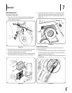
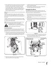
Gear Case
The auger gear case is equipped with a grease fitting. Lubricate
with Shell Alvania lead-free grease (737-0168) once a season. See
Figure 6-3.
NOTE: To relieve pressure, remove the vent plug before
lubricating the gear case. See Figure 6-3. Failure to do so could
result in damage to the gear case seals.
Augers
Each of the six auger spiral assemblies is secured to the spiral
shaft with a shear pin and cotter pin. If the auger should strike a
foreign object or ice jam, the snow thrower is designed so that
the pins may shear.
If augers do not turn, check to see if pins have sheared. 1.
Replace the pins if needed. Two replacement shear pins and 2.
cotter pins have been provided with the snow thrower.
Spray an oil lubricant into shaft before inserting new pins
and securing with new cotter pins.
Adjustments
Shift Rod
If the full range of speeds (forward and reverse) cannot be
achieved, refer to the figure to Figure 6-4 and adjust the shift rod
as follows:
Looking underneath the handle panel, note which of the three 1.
holes in the shift lever the ferrule is inserted into. Also note
the direction of insertion. Then remove the internal cotter
pin and flat washer from the ferrule and withdraw the
ferrule from the shift lever. See Figure 6-4.
Place shift lever in sixth (6) position or fastest forward speed.2.
Push shift rod and shift arm assembly down sharply as far as it 3.
will go to shift the drive into the fastest forward position.
As necessary, rotate the ferrule up or down the shift rod until 4.
the ferrule lines up with the hole from which it was earlier
removed. See Figure 6-4.
From the direction noted earlier, insert the ferrule into the proper 5.
hole. Reinstall the washer and secure with the internal
cotter pin.
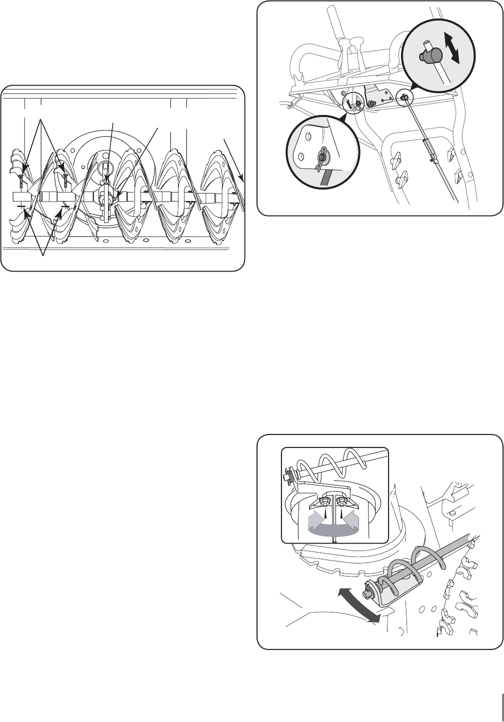
Chute Bracket Adjustment
If the spiral at the bottom of the chute directional control is not
fully engaging with the chute assembly, the chute bracket can be
adjusted. To do so:
Loosen the two nuts which secure the chute bracket and 1.
reposition it slightly. Refer to Figure 6-5.
Retighten the nuts.2.
Drive Control
Figure 6-4
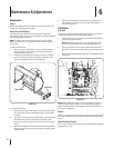
Figure 6-3
Shear Pin
Cotter Pin
Vent Plug
Gearbox
Lube Fitting
Lube Fitting
at Each End of
Auger Shaft
17se c t i O n 6 — Ma i n t e n a n c e & ad j u s t M e n t s