


WARNING! Do not over-tighten the cable. Over-
tightening may prevent the auger from disengaging
and compromise the safety of the snow thrower.
If adjusting the auger cable, thread the lock nut down to 4.
lengthen the cable as necessary to stop the auger from
turning when the control is released.
Securely hook the cable’s spring into the rear most hole of the 5.
respective actuator bracket.
Repeat the wheel drive and auger control tests to verify proper 6.
adjustment. Repeat previous steps if necessary to attain
proper adjustment of each cable
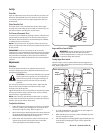
Gas & Oil Fill-Up
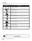
WARNING! Use extreme care when handling
gasoline. Gasoline is extremely flammable and the
vapors are explosive. Never fuel the machine indoors
or while the engine is hot or running. Extinguish
cigarettes, cigars, pipes and other sources of ignition.
Service the engine with gasoline and oil as instructed in the
separate Engine Owner’s Manual included with this unit. Read
those instructions carefully.
With the auger control in the disengaged “up” position, walk to 4.
the front of the machine.
Confirm that the auger has completely stopped rotating and 5.
shows NO signs of motion. If the auger shows ANY signs
of rotating, immediately return to the operator’s position
and shut off the engine. Wait for ALL moving parts to stop
before re-adjusting the auger control.
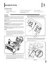
Testing Drive Control & Shift Lever
With the engine turned off, move the shift lever into sixth 1.
(6) position. Refer to Figure 3-8.
With the wheel drive control released, push the snow 2.
thrower forward, then pull it back. The machine should
move freely.
Engage the drive control and attempt to move the machine 3.
both forward and back, resistance should be felt.
Move the shift lever into the fast reverse (R2) position and 4.
repeat the previous two steps.
If you experienced resistance rolling the unit, either 5.
when repositioning the shift lever from 6 to R2 or when
attempting to move the machine with the drive control
released, adjust the drive control immediately. See
Adjusting Drive and Auger Controls.
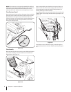
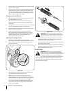
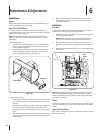
Adjusting Drive and Auger Controls
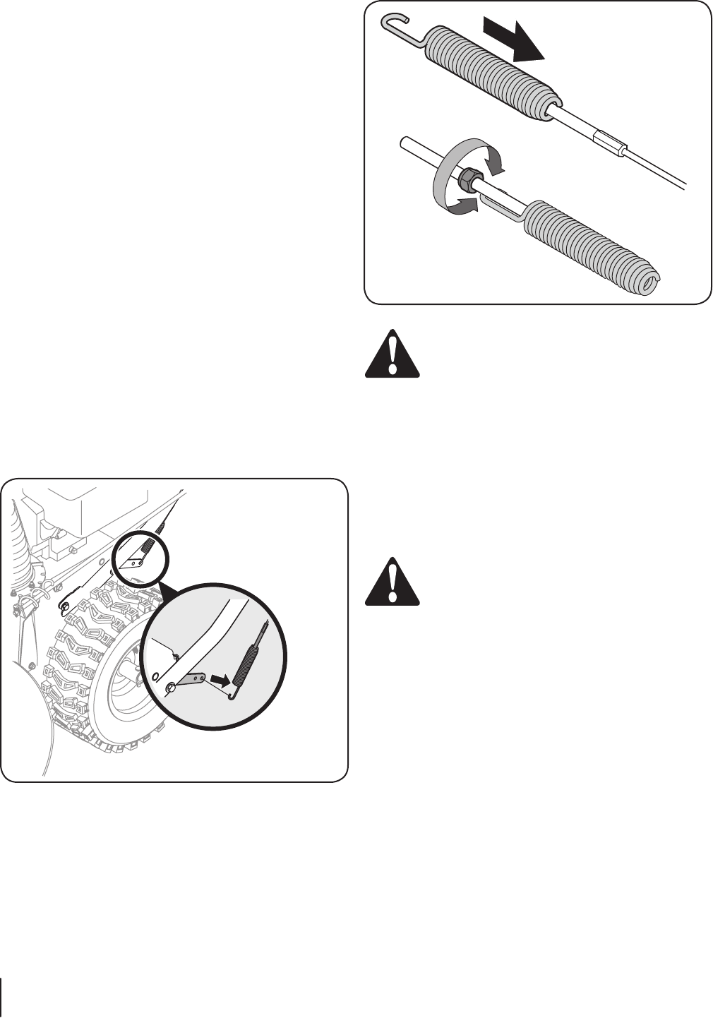
From beneath the handle, pull downward on the 1.
appropriate cable and unhook the spring found on the end
of the cable from its respective actuator bracket. Refer to
Figures 3-9 and 3-10.
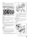
Slide the spring up the cable to expose the cable coupler 2.
threads and lock nut. Refer to Figure 3-10.
Adjust the lock nut as follows: If adjusting the drive 3.
cable, thread the lock nut outward (down the coupler) to
lengthen the cable and allow the unit to move freely when
the control is released. Thread the lock nut inward (up
the coupler) to shorten the cable to reduce slippage and
prevent the machine from being easily moved with the
drive control engaged.
Figure 3-9
Figure 3-10
10 se c t i O n 3— as s e M b l y & se t-up