


14
5
Making
Adjustments
WARNING
Read, understand, and
follow all instructions
and warnings on the
machine and in this
manual before operat-
ing.
Never attempt to
make any adjustments
while the engine is
running, except where
specified in operator’s
manual.
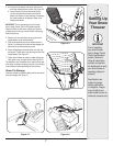
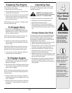
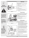
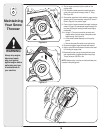
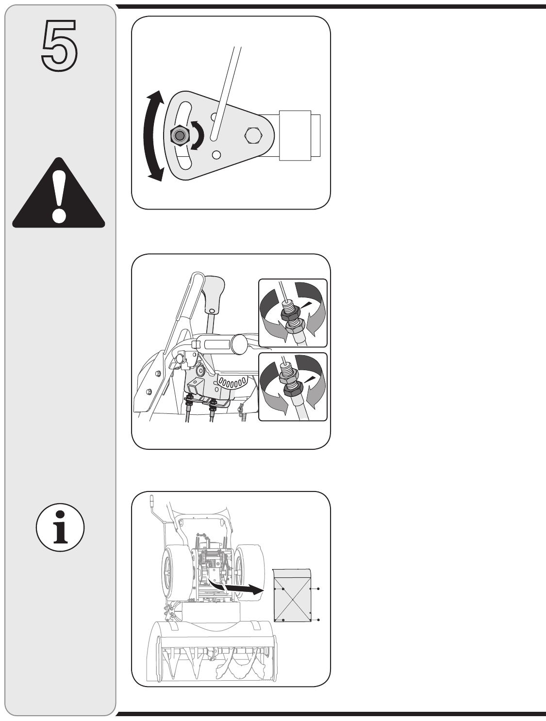
Shift Cable
If the full range of speeds (forward and reverse) cannot
be achieved, refer to the figure to the left and adjust the
shift cable as follows:
1. Place the shift lever in the fastest forward speed
position.
2. Loosen the hex nut on the speed selector pivot
bracket. See Figure 5-1.
3. Pivot the bracket downward to take up slack in the
cable.
4. Retighten the hex nut.
5. If further adjustment is needed, you may also utilize
the upper or lower hole in the pivot bracket.
6. Check for correct adjustment before operating the
snow thrower.
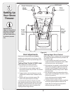
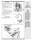
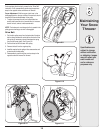
Chute Control
Once a season or every 25 hours of operation, whichever
is earlier, check whether the two-way chute control™
cables have slackened. If the chute pitch cannot be
moved up or down, the chute control cables will have to
be adjusted.
To adjust these cables, proceed as follows:
1. To tighten cable, loosen the top nut and tighten the
bottom nut on the cable.
2. Adjust equally on both sides by working on both
cables. See Figure 5-2.
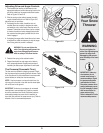
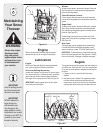
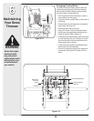
Drive Control
Refer to the Final Adjustment section of the Assembly
instructions to adjust the drive control. To further check
the adjustment, proceed as follows:
1. With the snow thrower tipped forward (be certain to
drain gasoline or place plastic film under the gas cap if
the snow thrower has already been operated), remove
the frame cover underneath the snow thrower by
removing the self-tapping screws. See Figure 5-3.
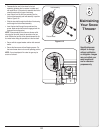
2. Locate the opening between the axle support bracket
and the front frame support (See Figure 5-4). Looking
through this opening, with the drive control released,
there must be 1/8” clearance between the friction
wheel and the drive plate in all positions of the shift
lever.
3. With the drive control engaged, the friction wheel must
contact the drive plate. See Figure 5-4.
4. If there is no friction wheel clearance, or the friction
wheel does not solidly contact the drive plate, re-
adjust the lock nut on the lower end of the drive cable
following the instructions in the Assembly section.
5. Reassemble the frame cover.
NOTE: If you placed plastic film under the gas cap earlier,
remove it now.
Figure 5-1
Figure 5-2
Figure 5-3
Specifications are
subject to change
without notification
or obligation. Images
may not reflect your
exact model and
are for reference
purposes only.