


20
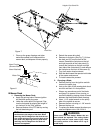
5. Jump Starting
a. Attach the end of the red jumper cable to the
Positive terminal (+) of the charged battery.
b. Attach the other end of the red jumper cable to
the Positive terminal (+) of the low charge bat
-
tery.
c. Attach the end of the black jumper cable to the
Negative terminal of the charged battery.
d. Attach the other end of the black jumper cable
to the frame of the unit with the low charge
battery.
6.
Fuses:
There are two fuses located in the wiring
between the ignition and start switch and other
electrical components. These are standard plug-
in type automotive fuses rated at 20 and 30 amp.
7.
Safety Switches:
There are three safety
switches in the electrical circuit which control the
engine. They are (1) the blade clutch switch, (2)
the steering lever/parking brake switch, and (3)
the seat switch.They operate so that in order to
start the engine, the blade clutch switch must be
off, the parking brake must be engaged, and both
steering levers must be in the neutral position.
Once the engine is started, the seat must be
occupied and the parking brake must be released
before either of the steering levers can be moved.
Also, the seat must be occupied before the blade
clutch switch can cause the blades to rotate.
8.
Safety Switch Operation Checks:
The following
operational checks should be made daily.
a. Blade Clutch Switch: Sit in the operator’s
seat. With both steering levers in the neutral
position and the parking brake engaged, turn
the blade clutch switch “on” and try to start the
engine. The engine should not start. If it does,
the blade clutch switch must be replaced. If
the engine does not start, turn the blade
clutch switch “off” and start the engine. Now
turn the blade clutch switch “on” and the
blades should rotate. If the blades do not turn,
the blade clutch switch must be replaced, the
seat switch must be replaced or the electric
PTO clutch must be repaired.
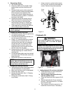
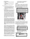
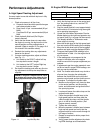
The air-gap should be checked every 100 hrs.
(or less, if severe operating conditions exist
such as when there are many on/off cycles,
mulching operations, material collection sys
-
tems used, and dusty/dirty conditions), and
the air-gap adjusted if more than 0.025". To
inspect, remove the “negative” cable from the
battery and all sparkplug wires. The air-gap
should be checked with feeler gages in the
three slots of the BBC (PTO Clutch). See
page 22 for air gap adjustment specs. There
are three inspection slots in the brake cover.
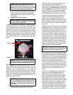
To adjust, successively tighten each of the
three gap adjustment nuts an equal amount.
Insert a feeler gage (see page 22 for specs)
into each slot as the air gap adjustment nut
are tightened. The correct adjustment occurs
when slight contact with the feeler gage
occurs. Engage the BBC (PTO Clutch) a cou
-
ple of times, and re-check the air-gap. If it is
not between the specs listed on page 22,
repeat the adjustment procedure.
b. Steering lever/Parking Brake Switch: Sit in
the operator’s seat. With both steering levers
in the neutral position and the blade clutch
switch “off”, release the parking brake and try
to start the engine. The engine should not
start. If it does, the parking brake switch must
be repositioned or perhaps replaced. If the
engine does not start, engage the parking
brake and start the engine.
c. Seat Switch: With both steering levers in the
neutral position, the parking brake engaged
and the blade clutch switch in the “off” posi
-
tion, start the engine. Now release the parking
brake, hold down on the back of the operator’s
seat against spring pressure. Release the
operator’s seat and the engine should stop. If
the engine does not stop, the seat switch must
be replaced. With both steering levers in the
neutral position, the parking brake engaged
and the blade clutch switch in the “off” posi
-
tion, sit in the operator’s seat and start the
engine. Turn the blade clutch switch to the
“on” position and the blades should start to
rotate. Raise up slightly off the operator’s seat
and the blades should stop. If the blades do
not stop when you dismount from the opera
-
tor’s seat, the seat switch must be replaced.
d. Electric PTO Clutch: This clutch operates
when the engine is running, the operator is in
the operator’s seat and the blade clutch switch
is turned on.This electric clutch is a fairly trou
-
ble free device. If a problem develops and the
blades do not turn, first check the 20 amp fuse
in the yellow, 16-gauge wire between terminal
“L” (for the Gasoline Engine) on the ignition
switch and the hour meter and then investi
-
gate the wiring harness and the connections
to the seat switch, the blade clutch switch and
the electric blade clutch. Then check out the
seat switch, the blade clutch switch and finally
the electric blade clutch.
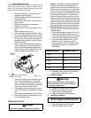
E.Tires
The two front wheels are caster wheels that are free to
swivel to accommodate the direction of the Mower.
The two rear wheels are used to propel the Mower in the
direction of input from the drive handles. Inflation
pressure of the rear tires is important for stability while
the Mower is in operation. If the tire diameter is not equal
between the two tires, the Mower will pull to one side.