


12
wheel, making the mower turn toward the side
where the lever is behind. When one lever is
pushed forward and the other lever pulled back
the same amount, one traction wheel will turn in
reverse and the mower will turn within its own
length.
In order to start the engine, both steering levers
must be in the neutral position; the parking brake
must be engaged; and the blade clutch switch
must be “off”. However, once the engine starts,
the parking brake must be released before the
operator places the steering levers into the
operating position or the engine will
automatically shut off.
Note: The Steering Lever will return toward
neutral when released, but they should be placed
in neutral by the driver. If the Drive Handles are
not placed in neutral, the tractor may creep.
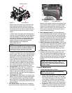
4.
Electric Blade Clutch Switch:
(See Figure 1.)
Located on the right side of the mower beside the
ignition switch. This is an “on/off” push pull switch
that controls the electric blade clutch which sup
-
plies power to the cutting blades through the
PTO. The switch must be turned off to start the
engine and should be turned off for safety any
time another person approaches the mower or
the mowing deck is raised to the transport posi
-
tion. Power to the electric clutch will also be cut
off if the operator leaves the operator’s seat.
5.
Parking Brake:
(See Figure 2.) Located on the
left side of the traction unit. The handle is an
overcenter lever which applies the drum-type
brake on each drive wheel when the handle is
pulled to the rear. The brake must be engaged in
order to start the engine.
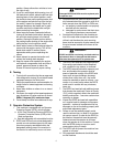
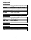
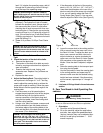
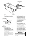
6.
Steering Levers
Foot Pedal Lift
Figure. 3
Foot Pedal Lift:
(See Figure 3.) Located on the
panel in front of the seat. Raise the mowing deck
to the transport position, by pushing the upper
part of the pedal. To lower the mowing deck, push
on the upper part of the pedal and lower it to the
desired position.
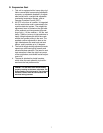
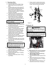
7.
Fuel Shutoff Valve:
(See Figure 4.) Located on
top of the fuel tank(s). When turned in a clockwise
direction until it stops, it will shut off the flow of fuel
to the engine. When turned in a counterclockwise
direction it will open and allow fuel to flow to the
engine. Close this valve if you are not going to run
the mower for a period of 30 minutes or more to
prevent flooding the engine.
Fuel Shutoff Valve
Figure. 4
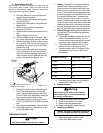
8.
Seat Adjustment Lever:
The Seat Adjustment
Lever is located beneath the seat. The Seat Adjust
-
ment Lever is used to move the seat forward and
backward. To place the seat in the desired position
pull the seat adjustment lever to the left then push
the seat forward or back to the desired position.
Release the lever so the seat will lock in place.
9.
Digital Tachometer and Hour Meter:
(See Figure
1) Located on the right side of the mower in front of
the ignition switch. When the machine is running
the tachometer displays engine rpm. When the
machine is off the tachometer displays running
time.
10.
Choke Lever:
(See Figure 1) The Choke Lever is
located on the left instrument panel next to the
seat. The Choke Lever is operated manually. Hav
-
ing the Choke Lever in the ON position helps the
engine to start during initial start-up. During normal
operation the Choke Lever should be in the OFF
position.
Note: There will be a flashing “LUBE” for each
recommended lubrication interval. There is a
flashing “OIL” at each recommended engine oil
and filter change.
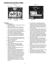
C.Initial Adjustments
1. Check the fluid levels and tires:
Note: These checks should be made daily,
before starting the engine.
a. Fuel: Using a good grade of unleaded, regular
gasoline (for a gasoline engine), fill the fuel
tank (beside the engine on the left or right side
of the mower). When the fuel reaches one
inch from the top of the tank, stop. DO NOT
OVERFILL. Space must be left for expansion.
b. Engine Oil: (Filled at the factory before ship-
ment.) Pull out the oil dipstick, wipe it off and
reinsert it. Pull it out again and read the oil