


42
SECTION 6: MOWER DECK
DECK LEVELING ADJUSTMENTS
The 60" mower deck is equipped with ground
following front caster wheels and is designed to be
operated with the front caster wheels and rear gauge
wheels on the ground. However, to ensure an even
cut on all types of terrain, the mower deck should be
properly leveled. To level the mower deck, proceed
as follows:
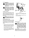
WARNING: Before leveling the mower
deck, position the tractor on a hard level
surface, engage the parking brake lever
and turn ignition key to the “OFF” posi-
tion. ALWAYS stop the engine after
utilizing the tractor hydraulic lift system.
When handling the mower deck, be care-
ful not to cut yourself on the sharp
blades.
Side To Side Leveling
NOTE: Check for proper tire inflation before checking
and/or making a leveling adjustment.
When the deck is properly leveled, the left and right
blades will have corresponding cutting-edge-to-
ground measurements within 1/16 inch of each other.
• Use the tractor hydraulic lift system to raise the
deck so that its wheels are off the ground. Stop
the engine.
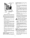
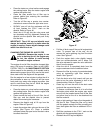
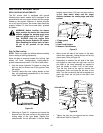
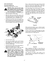
• Carefully rotate the outer cutting blades so that
they are positioned perpendicular to the tractor
frame. See Figure 50.
Figure 50
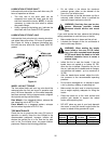
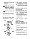
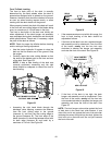
• Referring to Figure 51, measure and record the
distance from the level surface to the outer-most
cutting edge of the right blade. Repeat this
measurement for the left blade. If the two blade
heights are not within 1/16 inch, the deck must be
leveled. Note which blade had the larger
distance between the cutting edge and level
surface.
Figure 51
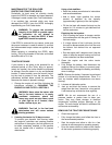
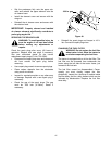
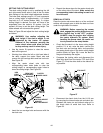
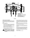
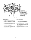
• Move to the left side of the tractor, to the deck
check chain assembly. Loosen the jam nut on the
check chain. Refer to Figure 52.
• Depending on whether the left side of the deck
was higher or lower than the right side, turn the
hex shaft of the chain assembly as needed to
level the blades to within 1/16" of each other.
Turn the hex shaft to the right to shorten the
adjustment chain and raise the left side of the
deck. Turn the hex shaft to the left to lengthen the
chain and lower the left side of the deck. See
Figure 52.
Figure 52
• Tighten the hex jam nut against the hex check
chain shaft. Refer to Figure 52.
OUTER BLADES
PERPENDICULAR TO FRAME
2
3
1
4
1.
Finger guard
2. Blade
3. Hard Level Surface
4. Measure This Distance
HEX
CHECK
HEX JAM NUT
CHAIN
SHAFT
SHORTEN
LENGTHEN