


20
stop when you dismount from the opera-
tor’s seat, the seat switch must be
replaced.
e.
Electric PTO Clutch:
This clutch operates
when the engine is running, the operator is
in the operator’s seat and the blade clutch
switch is turned on. This electric clutch is a
fairly trouble free device. If a problem
develops and the blades do not turn, first
check the 20 amp fuse in the yellow, 16-
gauge wire between terminal “L” on the
ignition switch and the hour meter and then
investigate the wiring harness and the con-
nections to the seat switch, the blade
clutch switch and the electric blade clutch.
Then check the seat switch, the blade
clutch switch and finally the electric blade
clutch.
f. No Cut in Reverse Switches:
When both
speed/direction levers are moved past
“neutral” to reverse the PTO Clutch will be
deactivated and the mower blades will stop
rotation. The PTO will be reactivated when
one or both of the levers are moved back to
“Neutral”.
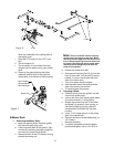
E.Tires
The two front wheels are caster wheels that are free
to swivel to accommodate the direction of the mower.
The two rear wheels are used to propel the mower in
the direction of input from the drive handles. Inflation
pressure of the rear tires is important for stability
while the mower is in operation. If the tire diameter is
not equal between the two tires, the mower will pull to
one side.
1.
Inflation Pressure:
a. Traction Tires—20 psi max; 8-10 psi rec-
ommended
b. Front Caster Wheel—28 psi max; 20-25
psi recommended
c. Cutting Deck Ball Wheels—Solid Polyure-
thane.
Use the Following guidelines for maintaining the tires:
a. Balance inflation pressure between the
rear tires to help maintain straight travel
(see tire side wall for proper inflation pres-
sure).
b. Keep the valve caps tightened to prevent
air pressure loss.
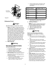
2.
Leaking Tires:
When a flat tire occurs, repair
or replace immediately. The normal procedure
is to remove the wheel and replace it. If a tire
is getting soft, park the mower on the nearest
level, paved area. If the leaking tire is on a
traction wheel, put blocks on each side of the
opposite traction wheel and jack up the tire
that leaks about an inch off the ground.
Loosen and remove the lug nuts and remove
the wheel. Mount a wheel and tire, replace the
lug nuts, and using a torque wrench, tighten
them to 60
±
10 ft-lbs.
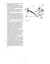
If the leaking tire is on a front caster wheel,
block both traction wheels and raise the
caster wheel so that the tire is an inch off the
ground. Loosen and remove the locknut from
the axle assembly and pull the axle assembly
from the caster yoke. The wheel and two
spacer sleeves will drop free. Slip the axle
assembly through one side of the caster
yoke, through a spacer sleeve, a wheel, the
other spacer sleeve and finally through the
other side of the caster yoke. Then tighten
the locknut on the end of the axle assembly.
Lower the mower off the jack and continue
mowing. The wheel with the leaking tire
should be inflated to 20 psi and the wheel
placed in a large bucket of water. Carefully
inspect the tire, rim and valve for escaping air
bubbles which indicate a leak. Mark each
leak with a yellow marking crayon and then
deflate the tire to 8 psi and repeat the
inspection. If the leaks you find are pin hole
size to 1/16" diameter, the tire can be
repaired. If the leaks are larger than 1/16"
diameter, the tire can be repaired. If the tire
bead is damaged, the tire can be repaired or
the tire will have to be replaced.
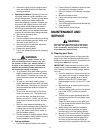
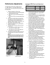
3.
Creeping:
Creeping is the slight forward or
backward movement of the mower when the
throttle is on and the lapbars are in the
opened-out position. If your mower creeps do
the following.
a. Jack up rear of unit.
b. Place Lapbars in neutral opened-out posi-
tion.
c. Locate jam nuts on transaxle control arms.
(They are on the vertical linkage on the
front of the transaxles)
d. Loosen jam nuts on both ends of rod con-
nectors.
e. Start unit and push throttle all the way on.
f. If unit creeps forward, rotate vertical rod
links counter-clockwise. If unit creeps in
reverse, rotate clockwise.
Adjust the appropriate rod connector. The
left rod for the left side of the mower and
the right rod for the right side of mower.
Afterward, retighten jam nuts.
F. Brakes
While the mower is in motion, all braking is performed
dynamically through the hydraulic pumps and traction
motors, controlled by the two steering levers. When the
mower is parked with the engine shut off, the hydraulic