


11
4.
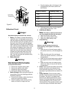
Electric Blade Clutch Switch:
(See Figure
1.) Located on the right side of the mower
beside the ignition switch. This is an “on/off”
push-pull switch that controls the electric
blade clutch which supplies power to the cut-
ting blades through the PTO. The switch must
be turned off to start the engine and should
be turned off for safety any time another per-
son approaches the mower or the mowing
deck is raised to the transport position. Power
to the electric clutch will also be cut off if the
operator leaves the operator’s seat.
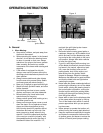
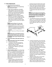
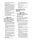
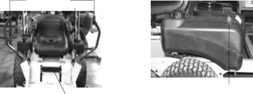
5.
Parking Brake:
(See Figure 3.) Located on
the left side of the traction unit. The handle is
an overcenter lever which applies the drum
brakes on the drive wheels when the handle is
pulled to the rear. The brake must be engaged
in order to start the engine.
6.
Deck Lift Handle:
(See Figure 3.) Located on
the panel in front of the seat. Raise the mow-
ing deck to the transport position, by pulling
the handle to the rear and moving it upward
for transport. To lower the mowing deck, pull
the deck lift handle to the rear and lower it to
the desired position.
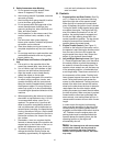
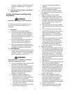
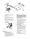
7.
Fuel Shutoff Valve:
(See Figure 4.) Located
on top of the fuel tank. When turned in a
clockwise direction until it stops, it will shut off
the flow of fuel to the engine. When turned in
a counterclockwise direction it will open and
allow fuel to flow to the engine. Close this
valve if you are not going to run the mower for
a period of 30 minutes or more to prevent
flooding the engine.
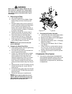
8.
Seat Adjustment Lever:
The Seat Adjust-
ment Lever is located beneath the seat. The
Seat Adjustment Lever is used to move the
seat forward and backward. To place the seat
in the desired position pull the seat adjust-
ment lever to the left then push the seat for-
ward or back to the desired position. Release
the lever so the seat will lock in place.
9.
Hour Meter:
(See Figure 1) Located on the
right side of the mower behind the ignition
switch. The hour meter displays running time.
Note:
There will be a flashing “LUBE” for
each recommended lubrication interval. There
is a flashing “OIL” at each recommended
engine oil and filter change.
10.
Choke Lever:
(See Figure 2) The Choke is
integrated into the throttle control which is
operated manually. Having the Choke in the
ON (full forward) position helps the engine to
start during initial start-up. During normal
operation the Choke should be in the OFF
(the detent for full throttle) position.
Brake
Steering Levers
Deck Lift Handle
Figure. 3
Fuel Shutoff Valve
Figure. 4