


20
a. Attach the positive (red) cable.
b. Attach the negative (black) cable.
c. Attach the rubber battery strap.
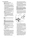
5. Jump Starting
Warning:
Failure to use this starting procedure can cause
sparking, and the gases in the battery to
explode.
a. Attach the end of the red jumper cable to the
positive terminal (+) of the charged battery.
b. Attach the other end of the red jumper cable
to the positive terminal (+) of the low charge
battery.
c. Attach the end of the black jumper cable to
the negative terminal of the charged battery.
d. Attach the other end of the black jumper
cable to the frame of the unit with the low
charge battery.
6.
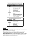
Fuses:
There is one fuse located in the wiring
between the battery and ignition start switch.
This is a standard plug-in type automotive fuse
rated at 20 amp.
7.
Safety Switches:
There are three safety
switches in the electrical circuit which control the
engine. They are (1) the blade clutch switch, (2)
the parking brake/lap bar switch, (3) the seat
switch.They operate so that in order to start the
engine, the blade clutch switch must be off, the
parking brake must be engaged, and both steer
-
ing levers must be in the neutral position. Once
the engine is started, the seat must be occupied
and the parking brake must be released before
either of the steering levers can be moved. Also,
the seat must be occupied before the blade
clutch switch can cause the blades to rotate.
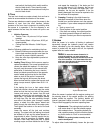
8.
Safety Switch Operation Checks:
The follow-
ing operational checks should be made daily.
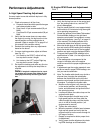
a. Blade Clutch Switch: Sit in the operator’s
seat. With both steering levers in the neutral
position and the parking brake engaged, turn
the blade clutch switch “on” and try to start
the engine. The engine should not start. If it
does, the blade clutch switch must be
replaced. If the engine does not start, turn
the blade clutch switch “off” and start the
engine. Now turn the blade clutch switch “on”
and the blades should rotate. If the blades do
not turn, the blade clutch switch must be
replaced, the seat switch must be replaced or
the electric PTO clutch must be repaired. The
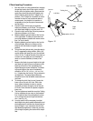
air-gap should be checked every 100 hrs. (or
less, if severe operating conditions exist such
as when there are many on/off cycles, mulch
-
ing operations, material collection systems
used, and dusty/dirty conditions), and the air-
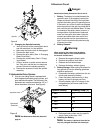
gap adjusted if more than 0.025". To inspect,
remove the “negative” cable from the battery
and all sparkplug wires. The air-gap should
be checked with feeler gages in the three
slots of the BBC (PTO Clutch). The air-gap
should be adjusted to 0.012" to 0.015". There
are three inspection slots in the brake cover.
To adjust, successively tighten each of the
three gap adjustment nuts an equal amount.
Insert a feeler gage (0.012" to 0.015") into
each slot as the air gap adjustment nut are
tightened. The correct adjustment occurs
when slight contact with the feeler gage
occurs. Engage the BBC (PTO Clutch) a cou
-
ple of times, and re-check the air-gap. If it is
not between 0.012" and 0.015", repeat the
adjustment procedure.
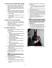
b. Parking Brake Switch: Sit in the operator’s
seat. With both steering levers in the neutral
position and the blade clutch switch “off”,
release the parking brake and try to start the
engine. The engine should not start. If it
does, the parking brake switch must be repo
-
sitioned or perhaps replaced. If the engine
does not start, engage the parking brake and
start the engine. Swing one steering lever up
to the operating position and the engine
should stop. If the engine does not stop, the
parking brake switch must be repositioned or
replaced.
c. Seat Switch: With both steering levers
opened-out to the neutral position, the park
-
ing brake engaged and the blade clutch
switch in the “off” position, start the engine.
Now release the parking brake, hold down on
the back of the operator’s seat against spring
pressure, and swing one of the steering
levers up to the operating position. Release
the operator’s seat and the engine should
stop. If the engine does not stop, the seat
switch must be replaced. With both steering
levers folded out in the neutral position, the
parking brake engaged and the blade clutch
switch in the “off” position, sit in the opera
-
tor’s seat and start the engine. Turn the blade
clutch switch to the “on” position and the
blades should start to rotate. Raise up slightly
off the operator’s seat and the blades should
stop. If the blades do not stop when you dis
-
mount from the operator’s seat, the seat
switch must be replaced.
d. Electric PTO Clutch: This clutch operates
when the engine is running, the operator is in
the operator’s seat and the blade clutch
switch is turned on. This electric clutch is a
fairly trouble free device. If a problem devel
-
ops and the blades do not turn, first check the
20 amp fuse in the yellow, 16-gauge wire
between terminal “L” on the ignition switch
and the hour meter and then investigate the
wiring harness and the connections to the