


12
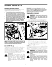
Seat Adjustment Lever
To adjust the seat forward or backward, slide the seat
adjustment lever to the left and reposition the seat to
the desired position. Once a comfortable position is
found, release the seat adjustment lever to lock the
seat in place. Refer to Seat Adjustment on page 18 of this
manual for more detailed instructions.
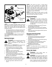
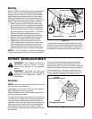
Deck Lift Lever
Found on your tractor’s right fender, the deck lift lever is
used to change the height of the cutting deck. To use,
move the lever to the left, then place in the notch best
suited for your application.
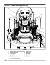
SECTION 5: OPERATING YOUR LAWN TRACTOR
WARNING: Read, understand, and follow
all instructions and warnings on the machine
and in this manual before operating.
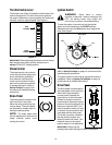
Safety Interlock Switches
This tractor is equipped with a safety interlock system
for the protection of the operator. If the interlock system
should ever malfunction, do not operate the tractor.
Contact a Cub Cadet dealer. The safety interlock
system prevents the engine from cranking or starting
unless the parking brake is engaged, and the PTO knob
is in the disengaged (OFF) position.
• The engine will automatically shut off if the operator
leaves the seat before engaging the parking brake.
• The engine will automatically shut off if the operator
leaves the tractor’s seat with the PTO knob in the
engaged (ON) position, regardless of whether the
parking brake is engaged.
• The electric PTO clutch will automatically shut off if
the PTO knob is moved into the engaged (ON)
position with the drive pedal in position for reverse
travel.
WARNING: Do not operate the tractor if the
interlock system is malfunctioning. This
system was designed for your safety and
protection.
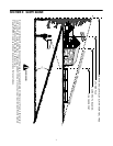
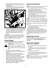
Setting the Gauge Wheels
Select the height position of the cutting deck by placing
the deck lift lever in any of the six different cutting height
notches on the right fender.
To adjust the deck wheels so that they are between ¼-
inch and ½-inch above the ground as follows.
WARNING: Keep hands and feet away
from the discharge opening of the cutting
deck.
NOTE: The deck wheels are an anti-scalp feature of
the deck and are not designed to support the weight of
the cutting deck.
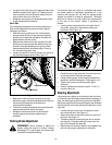
Place the tractor on a firm and level surface, preferably
pavement, refer to Figure 7, and proceed as follows:
• Place the tractor’s deck lift handle in the normally
desired mowing height setting, then check the
gauge wheels for contact or excessive clearance
with the surface below.
• If the wheels contact the surface adjust as follows:
a. Raise the deck lift handle to its highest
setting.
b. Remove the rear gauge wheels by removing
the lock nuts, shoulder screws, and flat
washers which secure them to the deck.
c. Remove the lock nuts, shoulder screws, and
bell washers which secure the front gauge
wheels to the deck.
d. Place the deck lift handle in the desired
mowing height setting.
e. Insert the shoulder screw and flat washer
with the rear gauge wheel into the index hole
that leaves approximately 1/2" between the
bottom of the wheel and the pavement.
f. Note the position of the index hole used; then
install the other rear gauge wheel and the
front ball wheels into the corresponding index
hole of the other gauge wheel brackets.
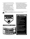
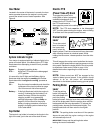
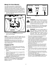
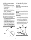
AVOID SERIOUS INJURY OR DEATH
• GO UP AND DOWN SLOPES, NOT ACROSS.
• AVOID SUDDEN TURNS.
• DO NOT OPERATE THE UNIT WHERE IT COULD SLIP OR TIP.
• IF MACHINE STOPS GOING UPHILL, STOP BLADE(S) AND BACK
DOWNHILL SLOWLY.
• DO NOT MOW WHEN CHILDREN OR OTHERS ARE AROUND.
• NEVER CARRY CHILDREN, EVEN WITH BLADES OFF.
• LOOK DOWN AND BEHIND BEFORE AND WHILE BACKING.
• KEEP SAFETY DEVICES (GUARDS, SHIELDS, AND SWITCHES) IN
PLACE AND WORKING.
• REMOVE OBJECTS THAT COULD BE THROWN BY THE BLADE(S).
• KNOW LOCATION AND FUNCTION OF ALL CONTROLS.
• BE SURE BLADE(S) AND ENGINE ARE STOPPED BEFORE PLAC-
ING HANDS OR FEET NEAR BLADE(S).
• BEFORE LEAVING OPERATOR’S POSITION, DISENGAGE
BLADE(S), ENGAGE BRAKE LOCK, SHUT ENGINE OFF AND
REMOVE KEY.
READ OPERATOR’S MANUAL
WARNING