


18
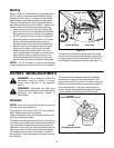
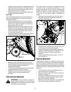
• Locate the two lock nuts on the opposite side of the
stabilizer bracket. See Figure 14. Tighten the lock
nuts to raise the front of the deck; loosen the lock
nuts to lower the front of the deck.
• Retighten the two jam nuts loosened earlier when
proper adjustment is achieved.
Side to Side
If the cutting deck appears to be mowing unevenly, a
side to side adjustment can be performed. Adjust if
necessary as follows:
• With the tractor parked on a firm, level surface,
place the deck lift lever in the top notch (highest
position) and rotate both blades so that they are
perpendicular with the tractor.
• Measure the distance from the outside of the left
blade tip to the ground and the distance from the
outside of the right blade tip to the ground. Both
measurements taken should be equal. If they’re
not, proceed to the next step.
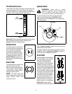
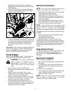
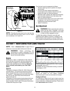
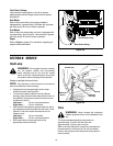
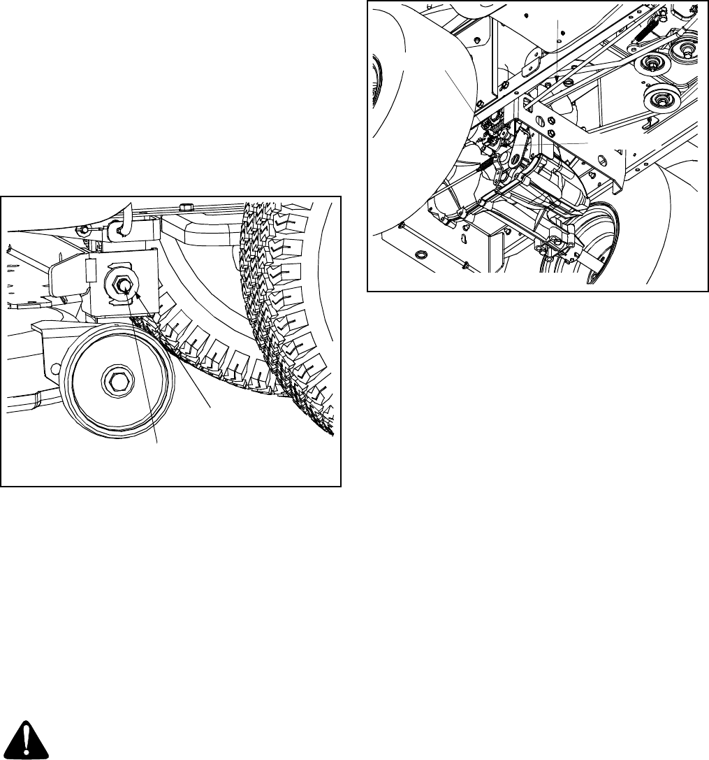
• Loosen, but do NOT remove, the hex cap screw on
the left deck hanger bracket. See Figure 15.
Figure 15
• Balance the deck by using a wrench to turn the
adjustment gear (found immediately behind the hex
cap screw just loosened) clockwise/up or
counterclockwise/down.
• The deck is properly balanced when both blade tip
measurements taken earlier are equal.
• Retighten the hex cap screw on the left deck
hanger bracket when proper adjustment is
achieved.
Parking Brake Adjustment
WARNING: Never attempt to adjust the
brakes while the engine is running. Always
disengage PTO, stop engine and remove key
to prevent unintended starting.
If the tractor does not come to a complete stop when
the brake pedal is completely depressed, or if the
tractor’s rear wheels can roll with the parking brake
applied, the brake is in need of adjustment. The brake
disc can be found on the right side of the transmission
in the rear of the tractor. Adjust if necessary as
follows.
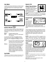
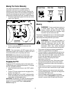
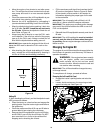
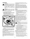
• Looking at the transmission from the right side of
the tractor, locate the compression spring and
brake disc. See Figure 16.
Figure 16
• Carefully remove the cotter pin from the crown nut
on the right side of the brake assembly.
• Using a feeler gauge, check the gap between the
brake disc and the brake puck. Proper gap is .011".
• Tighten the crown nut until the proper gap is
achieved.
• Insert a replacement cotter pin (part # 714-0111)
into the crown nut.
Steering Adjustment
If the tractor turns tighter in one direction than the other,
or if the ball joints are being replaced due to damage or
wear, the steering drag links may need to be adjusted.
Adjust the drag links so that equal lengths are threaded
into the ball joint on the left side and the ball joint on the
right side:
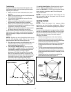
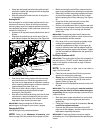
• Loosen the jam nut found on the drag link at the
rear of the ball joint. See Figure 17.
• Remove the hex nut and lock washer on the top of
ball joint. See Figure 17.
• Thread the ball joint toward the jam nut to shorten
the drag link. Thread the ball joint away from the
jam nut to lengthen the drag link.
• Replace hex nut and lock washer and retighten the
jam nut after proper adjustment is achieved.
Hex Cap Screw
Adjustment Gear
Brake Rod
Crown Nut
Brake Disc
NOTE: View shown from beneath tractor.