


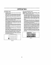


SERVICE AND ADJUSTMENTS
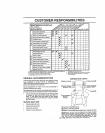
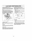
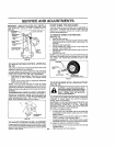
IMPORTANT; MAKE SURE UPPER BELT KEEPER tS
POSITIONED PROPERLY BETWEEN LOCATOR TABS
_ND ELECTRtO "CLUTCH WIRE CONNECTION IS
;ECURE.
ELECTRIC
CLUTCH _"'_.,
UPPER BELT_
KEEPER /
LOCATOR "'"
TABS
CLUTCHING "_''"
IDLER
STATIONARY
IDLER
TRANSMiSSiON*',-.
iNPUT PULLEY
_CLUTCH LOCATOR
1i,,
if,?, HARNESS
FIG, 29
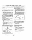
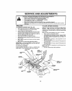
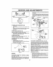
TO ADJUST MOTION CONTROL LEVER (See
Fig, 30)
The motion con=rot lever has been preset atthe factory and
adjustmenl should nst be necessary,
If for any reason the motion control tever will no! hotd Its
pesltloe while at a selected speed, it may be adjusted at the
friction pack located on the right side of transmission.
• Park tractor on level surface Stop tractor by turning
ignition key to "OFF" position, and engage parking
brake.
• Adjust motion control lever by tightening adjustment
locknut one hall (1/2) turn
NOTE: If for any reason the eftod Io move the motion
control lever becomes too excessive, reverse the above
adjustment procedure by loosening ]ocknut 1/4 to 1/2 turn.
Road test tractor after adjustment and repeat procedure if
necessary
TRANSMISSION REMOVAL/REPLACEMENT
Should your transmission require removat for service or
replacement, tt should be purged after retnstatlatfon and
before operating the tractor. See "PURGE TRANSMtS*
SION" in the Operation section of this manual
tf %:'
_,.. ADJUSTMENT
LOCKNUT
FIG, 30
TO ADJUST STEERING WHEEL ALIGNMENT
!1steering wheel crossbars are not horizontal (Ieft to dgh0
when wheels are positioned straightforward, remove sleep
ingwheat and reassemble per InstrUctionsinthe Assembly
section of this manual
FRONT WHEEl. TOE4NICAMBER
The front wheel toe-in and camber are not adiustable on
your tractor, tf damage has occurred to affect the front
wheel tee4n or camber, contact your nearest authorized
service center/department.
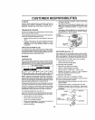
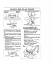
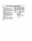
TO REMOVE WHEEL FOR REPAIRS
(See Fig. 31)
• Block up axle securely,
• Remove axle cover, retaining ring and washers toallow
wheel removal (rear wheel conlains a square key - Do
no! lose).
• Repair tire and reassemble
• On rear wheels only: align grooves in rear wheel hub
and axle.. Insert square key.
,, Replace washers and snap retaining ring securely in
axle groove.
• Replace axle cover,
NOTE: To seal tire punctures and prevent flat tires due to
slow leaks, tire sealant may be purchased from your local
parts dealer Tire sealanl also prevents tire dry rot and
corrosion.
WASHERS
RiNG
AX2OVER
_'"_BGUARE KEY
(REAR WHEEL ONLY)
FIG, 31
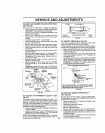
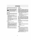
TO START ENGINE WITH A WEAK BATTERY
(See Fig° 32)
= i = =l m llll i H,,,,H,,,,,,I
l& CAUTION: Lead-acid batteries gener-
ate explosive gases,, Keep sparks, flame
and smoking materials away from bat-
terios, Always wear eye protection
when around batterles_
tf your battery ls too weak to start the engine, tt should be
recharged, tf "jumper cables" are used for emergency
starting, follow this procedure:
IMPORTANT: YOUR TRACTOR IS EQUIPPED WITH A 12
VOLT NEGATIVE GROUNDED SYSTEM THE OTHER
VEHICLE MUST ALSO BE A 12 VOLT NEGATIVE
GROUNDED SYSTEM, DO NOT USE YOUR TRACTOR
BATTERY TO START OTHER VEHICLES
TO ATTACH JUMPER CABLES -
• Connect each end of the RED cable to the POSITIVE
(+) terminal of each batten/, taking care not to shorl
against chassis,
• Connect one end of the BLACK cable Io the NEGA-
TIVE (-) terminal of lully charged battery
• Connect the other end of the BLACK cable to good
CHASSIS GROUND, awaylrom fuel tankand battery
TO REMOVE CABLES, REVERSE ORDER -
- BLACK cable first from chassis and then from the fully
charged battery
24 " RED cable last from both batteries