


SERVICE AND ADJUSTMENTS
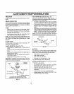
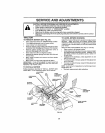
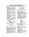
TO REPLACE MOWER BLADE DRIVE BELT
(See Fig. 26)
Park the tractor on level surface Engage parking brake
• Remove mower drive belt (See "TO REPLACE MOWER
DRIVE BELT" in this section ofthls manual)
• Remove mower (See "TO REMOVE MOWER" in this
section of this manual)
• Remove four screws from R H mandrel cover and
remove cover Unhook spring from bop on mower
housing
• Carefully roll belt oIf R H mandrel putley
• Remove beft from center mandrel pulley, idler pulley,
and L.Ho mandrel pulley
Remove any dirt or grass which may have accumu-
lated around mandrels and entire upper deck surface
• Check secondary idler arm and Idler to sea that they
rotate freety
• Be sure spring is hooked in secondary idler arm and
sway-bar bracket.
• Install new belt in lower groove of LH mandrel pulley,
fdter pulley, and cenler mandrel pu/tey as shown
• Rollbelt over R H mandrel pulley Make sure belt isln
all grooves properly
• Reconnect spring to bolt in mower housing and rein-
stall R H mandrel cover
• Reinstall mower to lractor (See "iNSTALL MOWER
AND DRWE BELT" in the Assembly section of this
manual)
• Reassemble mower drive belt (See "TO REPLACE
MOWER DRIVE BELT" inthis section o! this manual
MOWER
LH. BLADE CENTER
MANDREL DRIVE9ELT MANDREL
tDLER
R H,
MANDREL
COVER
SFR|NG
SWAY-eAR
BRACKET
SCREW
FIG. 26
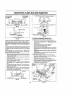
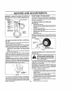
TO ADJUST ATTACHMENT CLUTCH (See
Fig, 27)
The eiectflc ctutch should provide years of service The
clutch has a built-in brake that stops the pultey within 5
seconds Eventually, the tntemat brake wilt wear which
may cause the mower btades to not engage, or, to not stop
as required Adjustments should be made by your nearest
authorized service center/department
• Make sure attachment clutch andignttton switches are
in "OFF" positron.
• Ad ust the three nylon Iocknuls unlit space between
clutch plate and rotor measures O12" at all three slot
tocalions cut in the side of brake plate.
NOTE; After installing a new electric clutch, run tractor at
full throttle and engage and disengage electric clutch 10
cycles to wear In clutch plate
ROTOR CLUTCHF.LATE
NYLON_SL_ _eRAKE
LOCKNUT(3) PLATE
FIG. 27
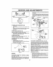
TO ADJUST BRAKE (See Fig. 28)
Your tractor is equipped with an adjustable brake system
which is mounted on the side of the transaxle
if _ractor requires more than six (6) feet stopping distance
at high speed inhtghesl gear, then brake must be adjusted
• Depress c]ulchibraka pedal and engage parking brake.
• Measure d{stance between brake operating arm and
nut "A" on brake rod
• II distance is other than 1-3/4% loosen jam nut andturn
nut "A" until distance becomes !-3/4" Retlghten iam
nut against nut "A".
• Roadtest tractor forproper stopping distance asstated
above, Rsadjusl if necessary. If stopping distance is
stil!greater than six (6) leel tn highest gear, further
maintenance is necessary Contact your nearest au-
thorized service center/department
WITH PARKING BRAKE "ENGAGED"
HUT "A'"-_._.__, JAM NUT
-77_;__ OPERATING
DONOTTOUCHTHt5NUT. IFFURTHER;BRAKeADJUST-
MENT|SNECESSARYCONTACTYOURNEARESTAUTHO-
R|ZEDSERVICECENTER!DEPARTMENT
F|Go 28
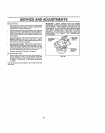
TO REPLACE MOTION DRIVE BELT
(See Fig. 29)
Park the tractor on leve_ surface Engage parking brake
For assistance, there is a belt installation guide decal on
bottom side of]elt footres_
• Remove mower (See "TO REMOVE MOWER" in this
section of this manual )
• Disconnect clutch wire harness
• Remove clutch locater
• Remove upper belt keeper
• Remove be_t from stationary idler and clutching Idler
• Pull belt slack toward rear of tractor Carefully remove
bait upwards from transmission input pu!ley and over
cooling fan biades
Pull belt toward frontof tractor and remove downwards
from around electric clutch
Insta!l new be]t by reversing above procedure
23"