


iii,i, IIIIHIIlll ii
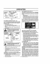
SERVICE AND ADJUSTMENTS
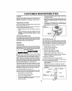
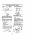
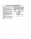
BOTTOM EDGE
OF MOWER TO
GROUND
BOTTOM EDGE
OF MOWER TO
GROUND
FIG. 21
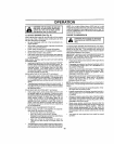
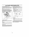
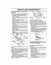
_(_ SUSPENSIONARM
. /
LIFT LiNK ADJUSTMENT NUT
FIG_ 22
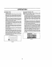
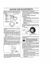
FRONT-TO-SACK ADJUSTMENT (See Figs 23 and 24)
IMPORTANT: DECK MUST BE LEVEL SIDE÷TO-S_DE _F
THE FOLLOWING FRONT-TO-BACK ADJUSTMENT IS
NECESSARY, BE SURE TO ADJUST BOTH FRONTLINK8
EQUALLY SO MOWER WILL STAY LEVEL SIDE-TO-
SIDE,
To obtain the best cutting results, the mower housing
should be adjusted sothat the front is approximately 118"to
1/2" lower than the rear when the mower is in its highest
position,
Check adjuslment on right side of tractor Measure dis-
tance "D" directly in front and behind the mandrel atboltom
edge of mower housing as shown
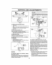
BOTHFRONTLINKSMUSTBE EQUALINLENGTH
NUT "E"
NUl
FIG. 24
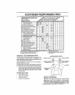
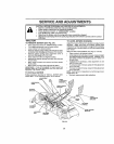
TO REPLACE MOWER DRIVE BELT
MOWER DRIVE BELT REMOVAL (See Fig, 25)
, Park!rector on a level surface Engage parking brake.
• Remove four screws from L,H mandrel cover and
remove cover,
• Roll beIt over the top of L H, mandrel pui_ey,
• Remove belt from electric clutch pulley.
• Remove belt from tdter pulleys,
Remove any dirt or grass clippings which may have
accumulated around mandrels and entire upper deck
surface,
• Check primary idler arm and two idlers to see that they
rotate freely,
• Be sure spdng ts securely hooked to primary idler arm
and bolt in mower housing,
• Before making any necessary adjustments, check that
both fron! links are equalin tenglh Both links should be
approximately 10-3/8",
• tf links are not equal in length, adjust one link to same
Ieng[h as other link,
• To lower front of mower loosen nut "E" on both front
links an equal number of turns
• When distance "D" is 1/8" to 1/2" lower at front than
rear, tighten nuts "F" against trunnion on both front
links.
• To raise front of mower, loosen nut"F" from trunnion on
both front links. Tighten nut "E" on both front links an
equal number ol turns
• When distance "D" is 1/8" to 1/2" lower at front than •
rear, tighten nut"F" against trunnion on both front links.
Recheck side-to-side adjustment.
:,_,,,% t _=,_ MANDREL
FIG, 23
MOWER DRIVE BELT INSTALLATION (See Fig, 25)
• Install be{t in both idlers, Make sure belt. is in both belt
keepers at the idlers as shown
• Install new belt onto electric cFutch puItey,
• Roll belt into upper groove ol LH mandrel pulley
. Carefully check bell routing making sure belt ls in the
grooves correctly and inside belt keepers
Reassemble LH. mandrel cover
ELECTRIC
CLUTCH
PULLEY
22 FIG. 25