


3
Call 1-866-576-8388 for missing parts or assembly help
DO NOT RETURN TO STORE
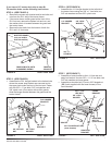
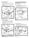
FIGURE 5 RIGHT SIDE VIEW
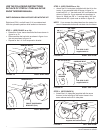
FIGURE 4 RIGHT SIDE VIEW
STEP 5: (SEE FIGURE 5)
• Assemble the R.H. hanger bracket to the bottom hole
where the mower stop bracket was removed and to
the upper hole under the front of the foot rest. Fasten
with two 3/8" x 1" hex bolts, 3/8" lock washers and
3/8" nylock nuts. (On tractors with mufer guards,
slide the hanger bracket between the guard and the
tractor frame.)
STEP 4: (SEE FIGURE 4)
• Remove the mower stop bracket and its two bolts and
nuts from the R.H. side of the tractor frame.
• If the tractor has a mufer guard at the front of the
R.H. foot rest, remove the bottom bolt and nut, and
the washer which is located between the guard and
the tractor frame.
• Remove the two bolts from the bottom of both the
R.H. and L.H. foot rests.
MUFFLER GUARD
(only on models
with side muffler)
REMOVE
BRACKET
REMOVE BOLTS, NUTS
& WASHERS SHOWN
3/8" x 1"
HEX BOLT
3/8" LOCK
WASHER
3/8" NYLOCK
NUT
R.H. HANGER
BRACKET
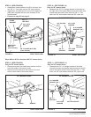
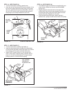
STEP 6: (SEE FIGURE 6)
• Assemble the L.H. hanger bracket to the left side of
the tractor frame using two 3/8" x 1" hex bolts, two
3/8" lock washers and two 3/8" nylock nuts.
FIGURE 7 LEFT SIDE VIEW
FIGURE 6 LEFT SIDE VIEW
STEP 7: (SEE FIGURE 7)
• Assemble a frame bracket to the L.H. foot rest and
sway bar bracket. Use two 3/8" x 1-1/4" hex bolts, two
3/8" lock washers and one spacer.
• Assemble a shoulder bolt (P) and a 3/8" anged nut
(BB) (both supplied with the snow thrower) to the
frame bracket.
3/8" x 1"
HEX BOLT
3/8" LOCK
WASHER
3/8" NYLOCK
NUT
L.H. HANGER
BRACKET
3/8" LOCK
WASHER
FRAME
BRACKET
3/8" x 1-1/4"
HEX BOLT
SWAY BAR
BRACKET
SPACER
SHOULDER
BOLT (P)
(snow thrower)
3/8" FLANGED NUT (BB)
(snow thrower)
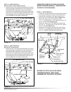
If you have a 54" mower deck skip to step #9.
For smaller decks use the following instructions.