


ASSEMBLY
Read these instructions and Operator's Manual in its en-
tirety before you attempt to assemble or operate your new
high pressure washer. Your high pressure washer has, for
the most part, been assembled at the factory, except those
parts left unassembled_ Before you can operate your new
high pressure washer, you must assemble the wheel kit and
properly connect the high pressure hose.
IF YOU HAVE ANY PROBLEMS WITH THE ASSEMBLY
OF YOUR PRESSURE WASHER, PLEASE CALL THE
PRESSURE WASHER HELPLINE AT 1-800-222-3136.
TOOLS REQUIRED FOR ASSEMBLY
,, Mallet
o 2 adjustable wrenches OR the following wrenches:
o 5/16" (8mm) combination wrench
* 1/2" (13mm) combination wrench
,, 11/16" (18ram) combination wrench
° 7/8" (22mm) combination wrench
o 15/16" (24mm) combination wrench
TO REMOVE PRESSURE WASHER FROM
CARTON
o Remove box for spray gun assembly and support legs
= Remove accessories box from carton.
° Remove wire basket (wrapped in plastic)
o Removeyour high pressure washer.
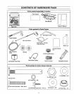
Refer to Page 6, "Contents of Hardware Pack" for an
illustrated listing of all items included with your pressure
washer. Become familiar with each piece before assem-
bling pressure washer. Check all contents against illustra-
tions on Page 6. If any parts are missing or damaged, call
Pressure Washer Helpline. at 1-800-222-3136.
HOW TO SET UP YOUR PRESSURE WASHER
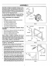
TO INSTALL THE WHEEL KIT
Installing the wheel kit requires the tools listed above, the
guide handle and items included in the parts carton.
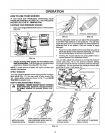
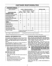
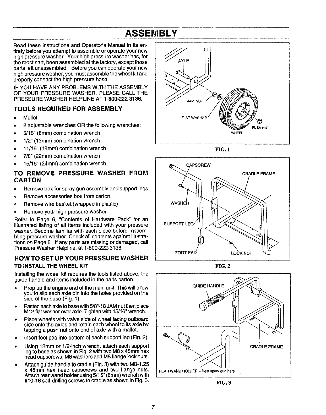
,, Prop up the engine end of the main uniL This will allow
you to slip each axle pin into the holes provided on the
side of the base (Fig. 1)
o Fasten each axle to base with 5/8"-18 JAM nut then place
M12 flat washer over axle. Tighten with 15/16" wrench.
= Place wheels with valve side of wheel facing outboard
side onto the axles and retain each wheel to its axle by
tapping a push nut onto end of axle with a malleL
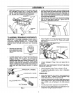
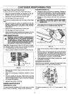
o Insert foot pad into bottom of each support leg (Fig. 2).
= Using 13mm or 1/2-inch wrench, attach each support
leg to base as shown in Fig. 2 with two M8 x 45mm hex
head capscrews, M8 washers and M8 flange lock nuts.
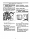
o Attach guide handle to cradle (Fig. 3) with two M8-1.25
x 45mm hex head capscraws and two flange nuts.
Attach rear wand holder using 5/16" (8mm) wrench with
#10-16 self-drilling screws to cradle as shown in Fig. 3_
FIG. 1
QAPSCR_
HEEL
CRADLE FRAME
WASHER
FOOT PAD
/
<
GUIDE HANDLE
REARWAND HOLDER - Restspraygun here
FIG. 3
CRADLE FRAME
7