


A ARNING: Always discon-
nect the spark plug wire and
place it where it cannot
make contact with spark plug to pre-
vent accidental starting when mak-
ing any adjustments or repairs.
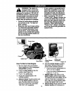
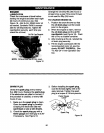
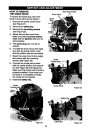
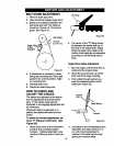
TO ADJUST SKID HEIGHT
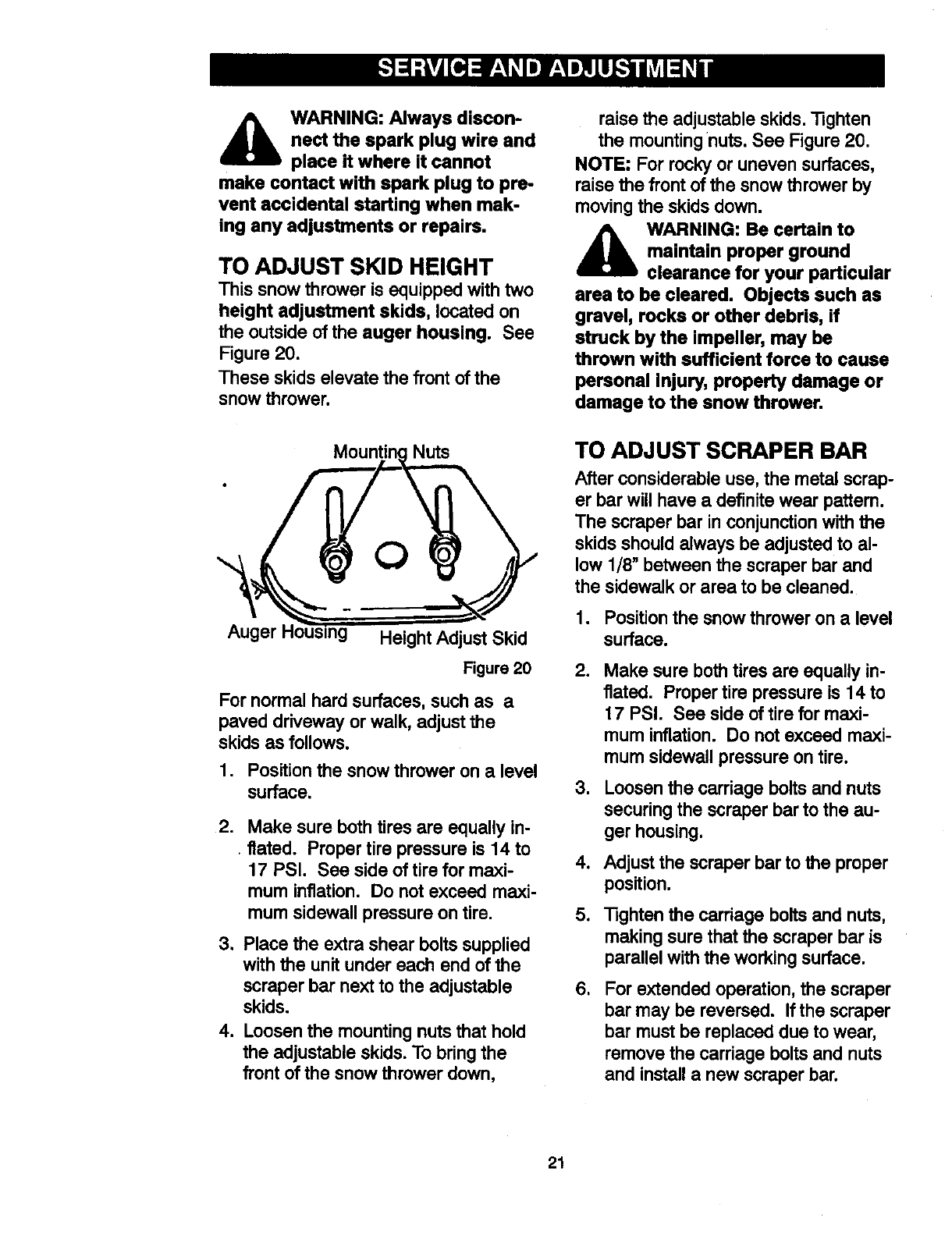
This snow thrower is equipped with two
height adjustment skids, located on
the outside of the auger housing. See
Figure 20.
These skids elevate the front of the
snow thrower.
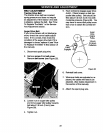
raise the adjustable skids. _ghten
the mounting nuts. See Figure 20.
NOTE: For rocky or uneven surfaces,
raise the front of the snow thrower by
moving the skids down.
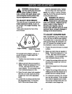
A ARNING: Be certain to
maintain proper ground
clearance for your particular
area to be cleared. Objects such as
gravel, rocks or other debris, if
struck by the impeller, may be
thrown with sufficient force to cause
personal injury, property damage or
damage to the snow thrower.
Nuts
. O
Height Adjust Skid
Figure20
For normal hard surfaces, such as a
paved driveway or walk, adjust the
skids as follows.
1. Position the snow thrower on a level
surface.
.
Make sure both tires are equally in-
flated. Proper tire pressure is 14 to
17 PSI. See side of tire for maxi-
mum inflation. Do not exceed maxi-
mum sidewall pressure on tire.
3. Place the extra shear bolts supplied
with the unit under each end of the
scraper bar next to the adjustable
skids.
4. Loosen the mounting nuts that hold
the adjustable skids. To bring the
front of the snow thrower down,
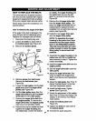
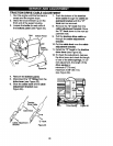
TO ADJUST SCRAPER BAR
After considerableuse, the metal scrap-
er bar will have a definitewear pattem.
The scraper bar in conjunctionwiththe
skids shouldalways be adjustedto al-
low 1/8" between the scraper bar and
the sidewalk or area to be cleaned.
1. Positionthe snow thrower on a level
surface.
.
Make sure both tires are equally in-
flated. Proper tire pressure is 14 to
17 PSI. See side of tire for maxi-
mum inflation. Do not exceed maxi-
mum sidewall pressure on tire.
3. Loosen the carriage boltsand nuts
securingthe scraper barto the au-
ger housing.
4. Adjust the scraper bar to the proper
position.
5. "13ghtenthe carriage boltsand nuts,
making sure thatthe scraper baris
parallelwith the workingsurface.
1
For extendedoperation, the scraper
bar may be reversed. If the scraper
bar mustbe replaceddue towear,
remove the carriage boltsand nuts
and installa new scraperbar.
21