


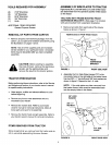
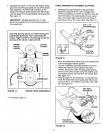
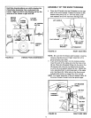
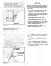
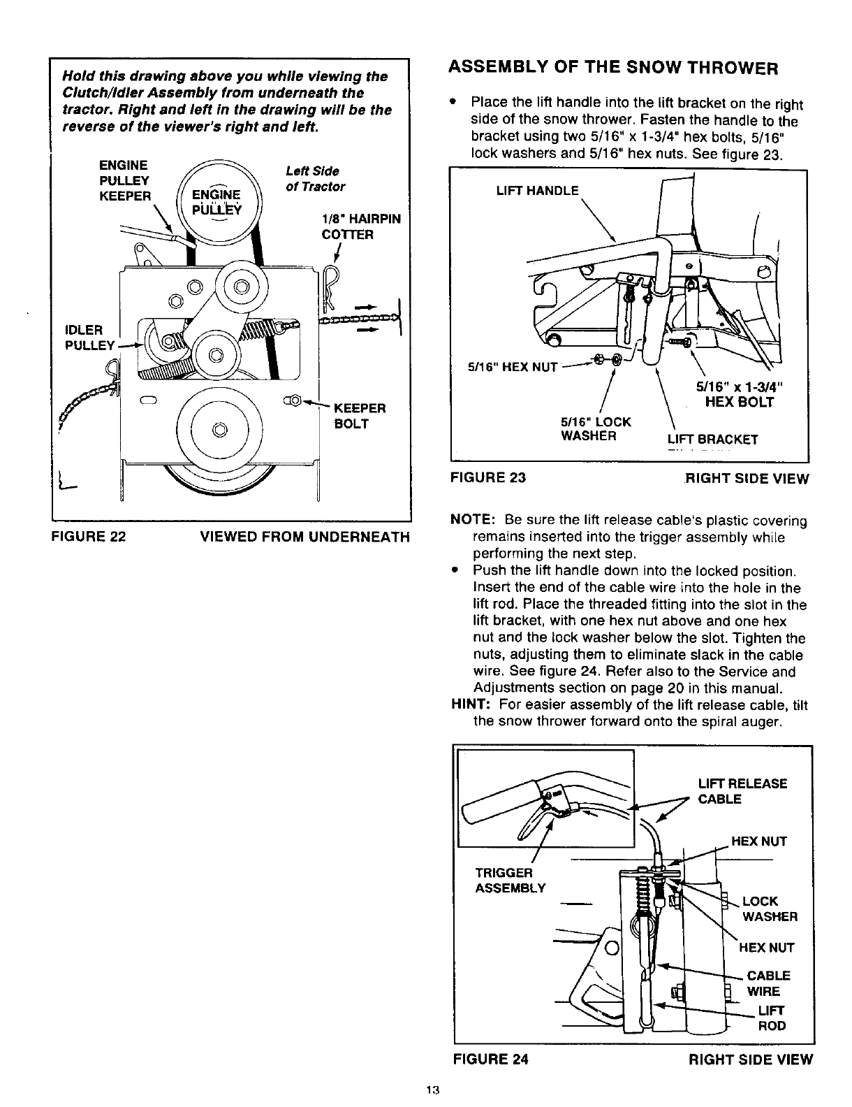
Hold this drawing above you while viewing the
Clutch/Idler Assembly from underneath the
tractor. Right and left in the drawing will be the
reverse of the viewer's right and left.
ENGINE Left Side
PULLEY of Tractor
KEEPER
1/8" HAIRPIN
COTTER
/
IDLER
L.
KEEPER
BOLT
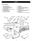
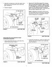
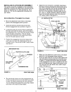
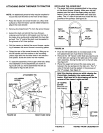
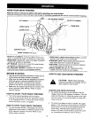
ASSEMBLY OF THE SNOW THROWER
Place the lift handle into the lift bracket on the right
side of the snow thrower. Fasten the handle to the
bracket using two 5/16" x 1-3/4" hex bolts, 5/16"
lock washers and 5/16" hex nuts. See figure 23.
LIFT HANDLE
\
5/16" HEX NUT "---"_ _'"
/
5116"LOCK
WASHER
5116" x 1-3/4"
HEX BOLT
LIFT BRACKET
FIGURE 23
RIGHT SIDE VIEW
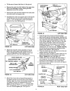
FIGURE 22 VIEWED FROM UNDERNEATH
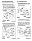
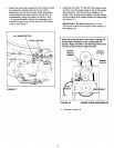
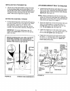
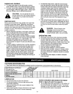
NOTE: Be sure the lift release cable's plastic covering
remains inserted into the trigger assembly while
performing the next step.
• Push the lift handle down into the locked position.
Insert the end of the cable wire into the hole in the
lift rod. Place the threaded fitting into the slot in the
lift bracket, with one hex nut above and one hex
nut and the lock washer below the slot. Tighten the
nuts, adjusting them to eliminate slack in the cable
wire. See figure 24. Refer also to the Service and
Adjustments section on page 20 in this manual.
HINT: For easier assembly of the lift release cable, tilt
the snow thrower forward onto the spiral auger.
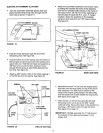
LIFT RELEASE
p1,.._ CABLE
_
\ WASRER
_'_\ l_r"_ _ _ CABLE
___WIRE
"-------.___LIFT
L__ __ - ROD
FIGURE 24 RIGHT SIDE VIEW
13